Contents

Navigate in 3D space using your mouse:
- Hold the right mouse button and drag to rotate the view around the rotation center (center of currently available scene objects by default)
- Scroll the mouse wheel to zoom in/out (zoom center = mouse position).
- Hold both mouse buttons and drag to move the view freely. Alternatively, you can use the keyboard arrow keys to move the view in the respective arrow directions.
- Click the middle mouse button / mouse wheel to center the view and set the clicked point as new rotation center.
| See the section 'Hotkeys' for a list of hotkeys that are available for the 3D viewer. |
For Windows 7 and 8, multitouch monitors are supported for 3D navigation:
- Use 3 fingers and drag to rotate the view.
- Use 2 fingers to move, or pinch to zoom.
- Use 1 finger to select the item under the finger or stylus, specify a point, or draw a curve.
Alternatively, 3D mice from 3dconnexion are also supported for navigation.
Showing/Hiding Objects
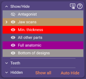
The "Group Selector" allows you to show or hide objects (like scan data, and constructed parts) by clicking the checkboxes left of the group description. Objects are grouped by type. For a more fine-grained selection, unfold a group by clicking on the little arrow left of the checkbox. As you proceed with the design, the list will become more and more populated.
A menu is available by right-clicking a group (e.g. right-click 'Anatomic shapes'). Among other things, this allows you to toggle transparency for an entire group of parts – a frequently used feature.
Unfold the 'Teeth' expander to switch visibility on a per-tooth basis. Unfold the 'Hidden' expander to see which parts are currently hidden. Use the 'Show all' button to show all parts available. Selecting Auto Hide will hide the opposing jaw when the current view direction is opposite to it.
| Instead of using the 'Show all' button, you can also hold the <ALT> key to temporarily show all parts. |
The Main Toolbar
The main toolbar presents options that are always available in the DentalCAD.
Save
Saves the current state of the CAD process in a "scene file" in the project folder. A scene file is a proprietary, version-specific file containing the complete state of the design process including scan information, current wizard step, and all modified settings and free-forming changes. To return to a specific point in the design if a design is likely to be revised, or for documentation of a design process, use 'Save scene as...' and label the specific design step. When reloaded, the CAD application appears exactly as it was. Alternatively, right-click the Save button to save the current CAD window as a 3D PDF, or as an open .stl file with all objects included.
Expert/Wizard
Toggles between Wizard and Expert mode of exocad DentalCAD.
After starting the CAD module, a "Wizard" window will open, which will guide you step by step through the construction. Explore the options presented to you in each wizard screen, and click 'Next' to proceed to the next step. Of course, you can always use the 'Back' button to return to previous steps in the wizard. The wizard will present you reasonable default values (depending on the type of construction and the material selected) for all construction parameters. You are free to change them; any parameters you change in the wizard will be applied to all teeth in the construction.
Advanced users often chose to temporarily suspend the wizard at some stages in the construction, and to use the context menu instead. This gives you the option to apply specific functions or parameters to specific teeth/objects on the screen. Note that while the wizard is running, only a simplified version of the context menu is displayed. In expert mode, you get access to all the options available at this particular stage of the design. Click the wizard button to return to the wizard, which will resume at the same step as when it was suspended.
Tools
- Measurement Tool - for measuring distance, thickness, or spacing for 3D objects on the screen.
- Sectional view - a way to "slice" through objects which may be obscured.
- Screen Shot - simple 2D screenshot, saved to the current project folder.
- PDF Export - export the current CAD view as a 3D PDF file, which can be viewed by anyone with the current version of Adobe reader.
- Share Scene Via dentalshare webview Link - to enable an efficient online collaboration exchanging cases from within the exocad software platform.
- HTML Export - Export scenes as an HTML file.
- DICOM Control – to view data from CT (Computerized tomography), CBCT (Cone beam computer tomography), or 3D X-Ray scan data sets (only in expert mode, and only if the module is installed).
- Jaw Movement - Load and visualize patient-specific jaw movement data
- Change Reconstruction Type - Change the reconstruction types of teeth.
- Align Meshes – A tool to align meshes enable matching between any mesh objects in the CAD window.
- Adjust Light - Change the virtual lighting in the DentalCAD scene.
- Annotation Editor - Add annotations to scene objects.
- Screenshot and Image Management – Collect, edit, or tag screenshots and improve communication and documentation.
- Add/Remove Mesh - Using this tool, you can add and/or remove meshes.
- Nesting – Open the CAM software and nest the reconstructions (only in expert mode, and only if the module is installed).
- Articulator - Enables the virtual articulation. (only in expert mode, and only if the module is installed).
- 2D Image Loader- Using this tool, you can add 2D images to your 3D scene.
- Tooth Color Selection - Display the restorations in natural tooth color.
- Smile Creator - Load patient photos and match to 3D scans of the teeth to create 2D and 3D esthetic smile makeovers.
- Show project in Explorer – Open the project folder.
- Settings - Allows configuration options for language, tooth numbering, graphics, user interface, GPU acceleration, and other settings.
- About - Shows the current version of the software and dongle ID.
Functional Selections
These additional CAD menu options only appear if the corresponding add-on module is installed, and the specified case requires them.
- Articulator - Toggles the virtual articulator control window.
- Show distances- Enables/disables the automatic distance coloring between opposing or adjacent teeth.
- TruSmile- Toggles realistic rendering of tooth restorations. You can access the additional modes
Plaster and Outline by right-clicking the TruSmile button in the main toolbar.
- Color/Texture - Available if the scan data contains color information. Toggles between color and
monochrome display of the scan data.
- Cut view - Opens a window showing a sectional view of your design.
- Smile window - Available after the Smile Creator has been used and enables an additional view of the current design relative to the patient photo during the CAD workflow
Add Custom View
Select 'Add custom view' to memorize the current viewpoint. Views are automatically named and listed below the 'Add View' button. To give the view a name, or rename a view, right-click the view. This is particularly useful for cases where multiple paths of insertion exist.
View Arrows
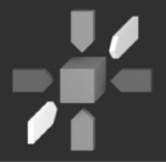
At the bottom of the main toolbar, view perspective buttons are available. Using the arrows, you can quickly view the scene from all six compass directions. These do not automatically correspond to anatomically correct directions of the scan data in the scene (depending on scanner and scanning software). Click on the cube to centrally display the currently set view perspective in its entirety.
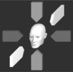
The cube changes to a human head if a scene from DentalCAD is loaded and the articulator has been previously performed.
The Context Menu
Context menus are available to help you explore what functions are available at a particular stage in the construction.
| If you are new to this software, you will not need to use the context menu at all. But as you get more familiar with the software, you will appreciate the options there. |
You can use the context menu to apply a certain function to:
- All teeth (the "root" context menu)
- Just one tooth (the "tooth-specific" context menu)
- A group of previously selected teeth
You can open the "root" context menu by right-clicking the background in the CAD window. Functions you select here will be applied to all suitable parts of the construction. In expert mode, the "root" context menu also gives you access to some advanced dialogs, such as 'Visual properties' and 'Edit mesh, useful for identifying and correcting non-ideal meshes.
By right-clicking an individual tooth in the viewer, you can open the tooth-specific context menu. Items you select here will be applied only to the tooth you clicked.
In expert mode, to apply a context menu function to a group of teeth (but not to all), hold <CTRL> and click the teeth to mark (note that the teeth will change color). Then, right-click the background to see the context menu for the marked teeth.
The context menu will adapt itself to the current state of the construction, so the menu entries you see vary during the course of the design. So if you're looking for a particular feature, it's always a good idea to explore the context menu. Note that while the wizard is running, only a stripped-down version of the context menu is available.
A pop-down menu is available when clicking the bottom edge of the CAD window. It provides access to the most commonly used context menu selections.
