Contents
Using the Align Meshes tool, you can match floating meshes on fixed meshes. This is typically used to align pre-op scans (floating mesh) to scan data (fixed mesh).
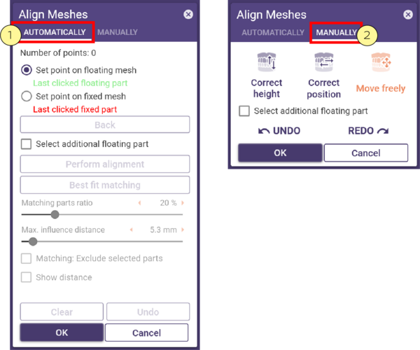
- Click Align Meshes to open the Align Meshes window.
- Select the type of alignment, Automatically [1] or Manually [2].
Automatically
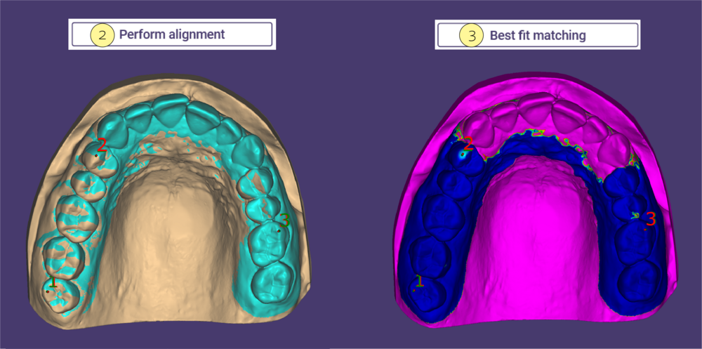
If you choose Automatically click alternating points at the same positions on the two meshes, as shown below:
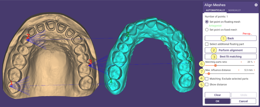
To undo an arrow, click Back [1]. When you have at least defined two point pairs, click Perform alignment [2].
Check Show distance [5] to display a color scale showing the remaining distance between the meshes. You can define the minimum and maximum distance.
The following functions help you to improve the alignment result:
- Using the slider Matching parts ratio [6], you can set the ratio of the surface parts existing on both surfaces. This means that only surface parts below the specified distance will influence the matching. With a higher value, the software tries to match surfaces that have a greater distance between the moving mesh and the fixed mesh. Large values (70-80%) may be more suitable for mesh pairs whose topology is to a large extent the same.
- Define the maximum influence distance using the slider Maximum influence distance [7]. Only surface parts below the specified distance will influence the matching. Important after performing point-to-point registration. A large value can worsen the result, since more surface parts from one surface are taken into account, which may not be present on the other surface.
In addition, the calculation often takes significantly longer.
- You can further improve the alignment result by clicking Best fit matching [3]. Only use best-fit matching when you have identically shaped meshes.
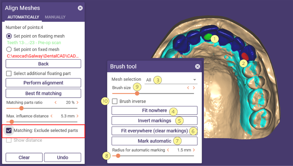
You can exclude mesh areas from best fit matching by checking Matching: Exclude selected parts [4]. This opens a Brush tool window.
Exclude selected parts
- Hold the left mouse button and drag to paint areas to be excluded from the matching (green tool) [1] , it will be colored blue. To clear the marking please hold the left mouse button and SHIFT (red tool) [2].
Mesh selection [3]: Select the mesh you want to draw areas on.
Fit nowhere [4]: Marks the complete mesh. Best-fit matching will have no effect.
Invert markings [5]: Marks unmarked areas vice versa.
Fit everywhere [6]: Clears all existing markings.
Mark automatic [7]: Uses only a small area around the tip and tail of each arrow as the matching region.
Radius for automatic marking [8]: Sets the radius of the mesh area at each arrow end.
Brush size [9]: Adjusts the size of the painting brush.
Brush inverse [10]: Inverts the brush functionality. You can also hold SHIFT while painting to inverse the brush.
Select additional floating parts
- You can select additional floating parts to be included in the alignment process by activating the checkbox Select additional floating parts [1]. This opens the Selected floating parts window.
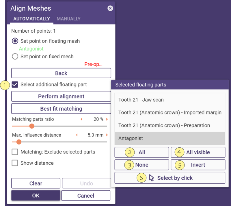 Select all parts in the list by clicking All [2].
Deselect all parts in the list by clicking None [3].
Select all visible parts in the list by clicking All visible [4].
Invert the current selection by clicking Invert [5].
Select by click [6] allows you to select individual parts by clicking them in the main view.
Hold CTRL while clicking to deselect a selected part.
Manually
If you choose Manually hold the left mouse button over the floating mesh and drag it to the desired position.
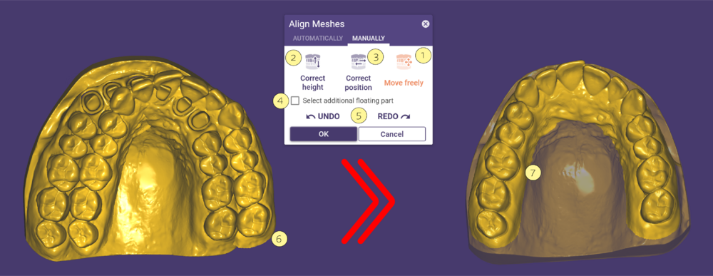 Move/rotate in all directions [1]: Allow freely movements of the model.
Move in z/direction [2]: Move vertically the direction.
Move in xy-plane [3]: Move horizontally the direction.
Select additional floating part [4]: Select additional floating parts to be included in the alignment process by activating the checkbox.
Undo and Redo [5]: Go back one step .
Drag the mesh with left mouse button [6] to the desired positon [7].
Additional floating part
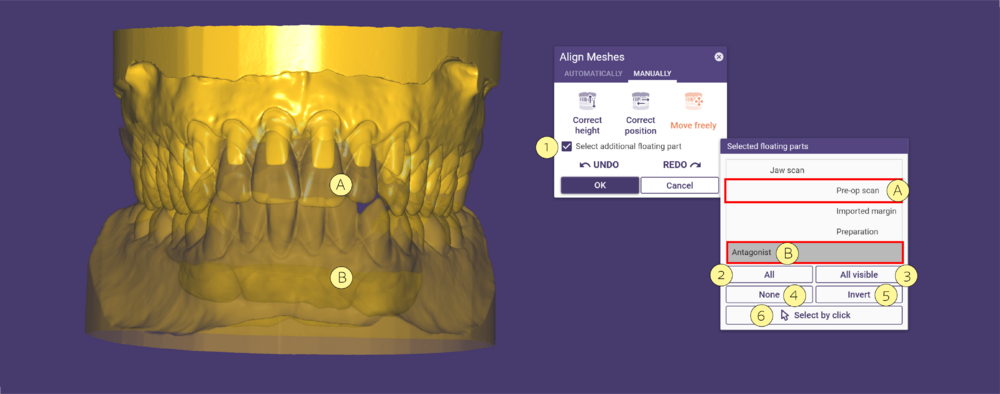
You can select additional floating parts to be included in the alignment process by activating the checkbox Select additional floating parts [1]. This opens the Selected floating parts window.
Select all parts in the list by clicking All [2].
Select all visible parts in the list by clicking All visible [3].
Deselect all parts in the list by clicking None [4].
Invert the current selection by clicking Invert [5].
Select by click [6] allows you to select individual parts by clicking them in the main view. Selecting [A] and [B] allows moving both meshes simultaneously.

