Contents
Using the Measurement Tool you can measure distances, angles, thickness, and object sizes.
NOTES:
- In general, the accuracy of dimensional measurements is 0.01mm while the accuracy of angular measurements is 0.5°. When measuring DICOM data, the accuracy is additionally limited by the voxel size.
- Only the Tools Distance and Angle can be used on CT Data. All other tools are instantly disabled when any measurement point is set on the CT data surface.
Measuring a Distance
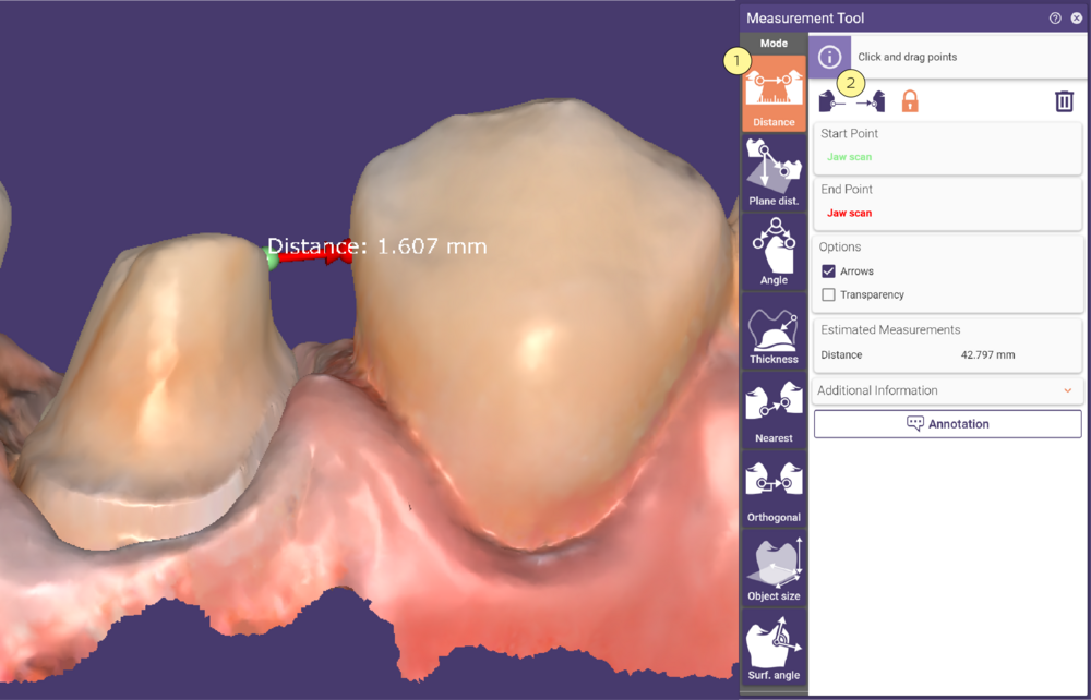
Activate Distance [1] and define the start and the end point by clicking the desired positions on the scene object(s). To redefine the points, either drag and drop them or select the corresponding button [2] at the top of the Measurement Tool window and click new positions.
Measuring Plane distance
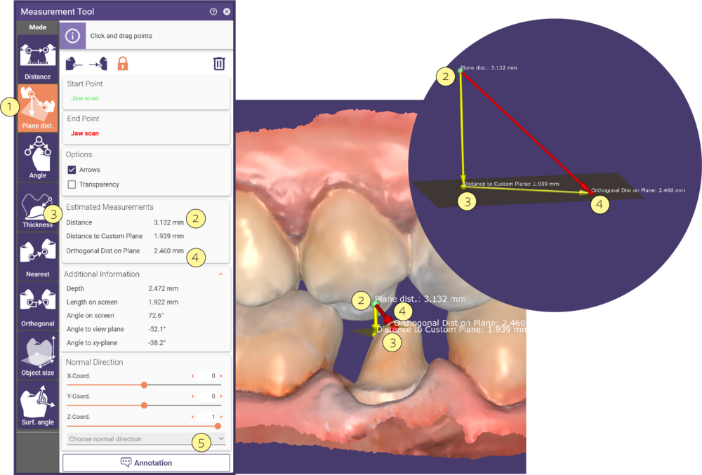
Activate Plane distance [1] to measure the perpendicular distance between the start point [2] and a custom plane [3], that has the normal vector direction of a user-selected designed part and passes through the distance’s end point [4]. You can select the direction of the normal from a drop-down menu that lists all tooth parts [5]. Note that the virtual plane level is not visualized in the 3D view.
Measuring an Angle
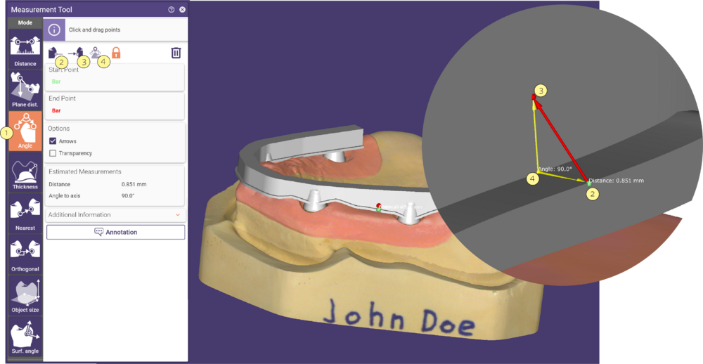
Activate Angle [1] and define the Start [2] and the End point [3] for a measurement. Define the angle center (yellow sphere) [4] by clicking the desired position on a scene object. To redefine the points, either drag and drop them or select the corresponding button [2] at the top of the Measurement Tool window and click new positions.
Measuring Thickness
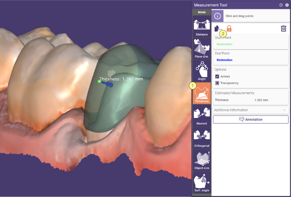
You can measure the local thickness of most of the generated mesh objects. Activate Thickness [1] and click a mesh object to define the start point (green). DentalCAD automatically selects the target point (blue) on the corresponding bottom/top part (e.g. crown bottom/top). If measuring the thickness of a finished reconstruction, start and target point will be on the same object. The thickness will be displayed at the arrow that indicates the measurement distance.
To redefine the start point, either drag and drop it, or select the corresponding button [2] at the top of the Measurement Tool window and click a new position.
Measure Nearest
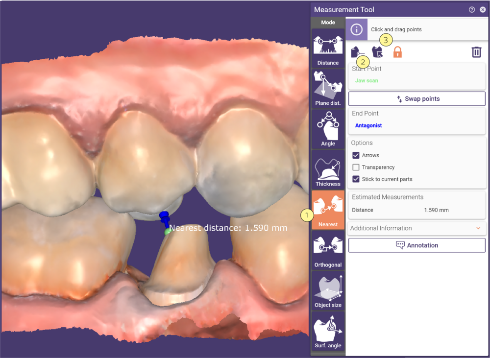
This function finds the nearest point of another surface to the selected point.Activate Nearest [1] and define the start point. Then, click the target object. If there are multiple target objects, select the desired object in the appearing menu. The closest point on the opposite side of the object is displayed as a blue point. An arrow shows the location of the calculated thickness.
To redefine the start point, either drag and drop it, or select the corresponding button [2] at the top of the Measurement Tool window and click a new position. To change the target object, click the Set target object icon [3], and click the new target.
Measuring Orthogonal
This function detects the nearest point on the nearest object perpendicular to the surface of the start point.
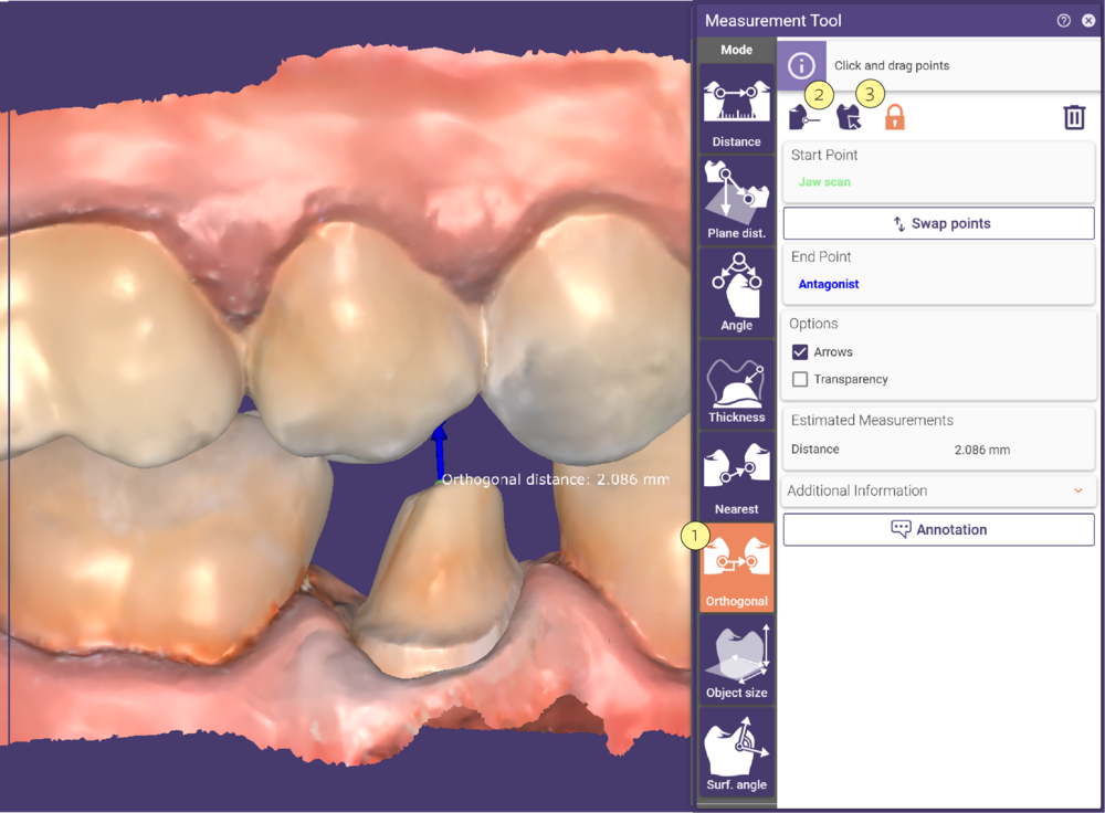
Activate Orthogonal [1] and define the start point. Then, click the target object. If there are multiple target objects on top of each other, select the desired object in the appearing menu. The closest orthogonal point will be displayed in blue.
An arrow shows the location of the calculated thickness. To redefine the start point, either drag and drop it or select the corresponding button [2] at the top of the Measurement Tool window and click a new position. To change the target object, click the Set target object icon [3], and click the new target.
Measuring Object Size
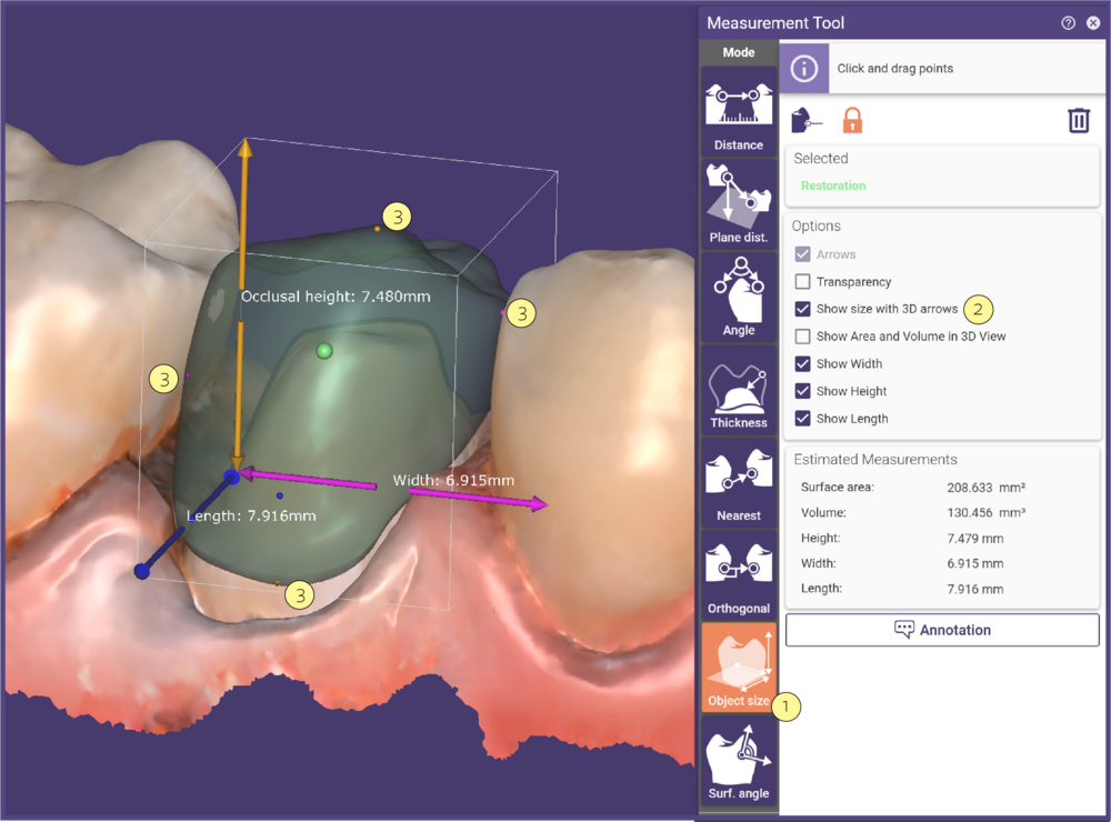 This function measures the length, width, and height of an object. Activate Object size [1] and click the object. Check Show tooth size with 3D arrows [2]. The object size is displayed with three arrows. This tool is most commonly used to measure teeth, so the length, width, and height are defined as mesial/distal (pink), occlusal height (yellow), and buccal/lingual (blue). Small colored points on the object surface [3] show the extremes that were used for the sizing calculation. Each small colored point corresponds to its measurement axis. To select a different object, drag the green start point to the desired object.
NOTE:The accuracy of object size measurements is 0.1mm.
Measuring the Angle of a Surface
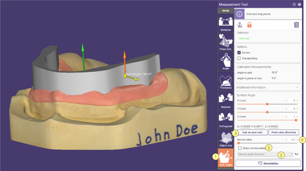
This function measures the angle surface relative to the normal direction of a restoration.
Activate Surf. Angle [1] and select the location by clicking on any of the scene objects and placing the yellow point on the desired position. The yellow arrow indicates the estimated angle from the orange arrow.
The orange arrow indicates the direction of the normal vector of the selected restoration. You can select the direction from the drop-down menu Choose angle direction [2].
The default vector direction is that of the scan data orientation. You can select a different vector direction from the available restorations.
- To change the normal vector direction manually, use the available sliders.
- Click the button Use as new axis [3] to convert the measured angle vector into a new normal vector direction.
- The Normal radius [4] slider allows you to broaden the area that will be used for the normal vector estimation at the desired position (yellow marker). You can display the size of the radius after checking the Show normal radius [5] option.
Common Functions
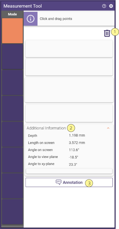
To clear measurements, click the bin icon [1].To view detailed information on measurements, expand the Additional Information section [2]. To create an annotation from a measurement, click the annotation button [3].
When available, activating the checkbox Define points by coordinates will display controls that allow coordinate editing:
You can change the coordinates of the selected point with the help of the X-Coord., Y-Coord. and Z Coord. sliders or by typing in the corresponding edit boxes. The coordinates will be updated depending on the selection of the measurement tool in use and the Start or End Point.

