Contents
Using this tool, you can add and/or remove meshes. Clicking Add/Remove Mesh opens the Add/Remove Mesh window.
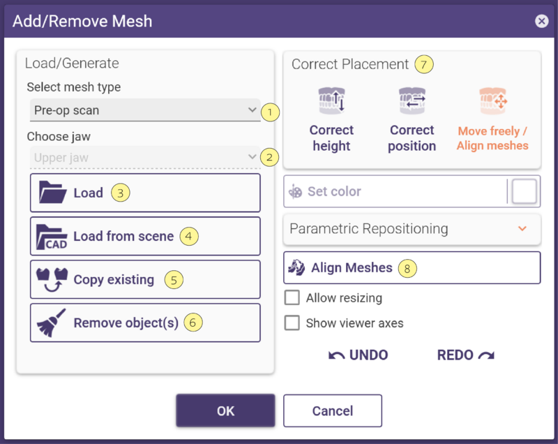
- Select the type of mesh you want to load from the Select mesh type [1] drop-down list.
- If required, e.g. if your projects contain restorations in both jaws, select the jaw you want to load a mesh for in the Choose jaw [2] drop-down list.
- Click Load [3] and select the mesh file in the appearing explorer window. Once selected, DentalCAD loads and visualizes the mesh. To remove a loaded mesh, click Remove object(s) [6].
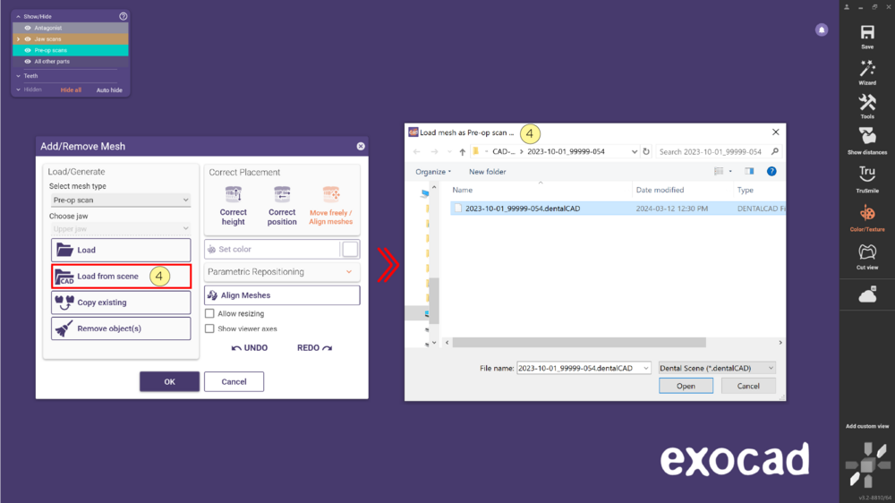
- Click [4] Load from scene to import objects from a saved scene.
- With the Copy existing [5] option, you can copy and convert parts from the current scene.
- If required, move the mesh using the mesh Correct Placement [7] options.
- Use the option Align Meshes [8]to align the imported file to the current scene.
Select mesh type
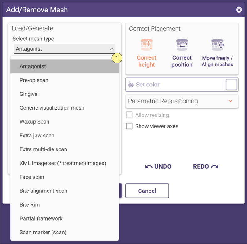 You can load the following meshes in DentalCAD using the Add/Remove Mesh tool (Expert mode only).
- Antagonist: If you already have an antagonist, DentalCAD will ask you if you want to replace it with the new antagonist mesh.
- Pre-op model: Scan of pre-operative situation (also known as situ-scan)
- Gingiva: Scan of the soft tissues.
- Generic visualization mesh: Any generic scan.
- Waxup Scan: Scan that allows the construction directly from the scan data.
- Extra jaw scan: Additional jaw scan. You can align this scan to the existing scan.
- Extra multi-die scan: Additional die scan. Align this scan to the existing die.
- XML image set (*.treatmentImages): Image including positioning information.
- Face scan: 3D face scan as a mesh object.
- Bite alignment scan: Scan of two jaws in occlusion. You can align this scan to the existing jaw scan.
- Bite rim: Scan of bite rims.
- Partial framework: Scan of a partial framework.
- Scan marker (scan): Scan of the marker that gives the implant position.
- Scan of substructure design: Scan of the substructure if you want to design a suprastructure.
Supported file formats: STL (Binary or ASCII), OFF (Binary or ASCII), OBJ ASCII, PLY, and open system .DCM mesh files, as well as Point Clouds (contact exocad for Point Cloud details).
Load from scene
| This feature is still marked as a Prototype for testing purposes but can already be very helpful in many cases. |
- After clicking Load from scene [4], select the scene followed by Open.
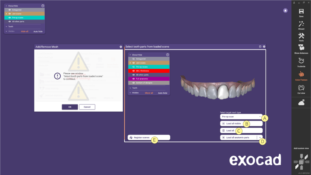
- The window Select tooth from loaded scene opens and you can now choose from:
- [A] Select target mesh type - Choose the type of mesh you will load.
- [B] Load all visible - Load all visible parts from the loaded scene into the current scene. Use the Group menu to show/hide a specific part.
- [C] Load all - Load all existing parts, including anatomic parts from the loaded scene into the current scene.
- [D] Load all anatomic parts - Load all the anatomic parts from the scene.
- [E]Register scene - Register meshes between the loaded and current scene using the align meshes tool. Use the Load button to import the registered meshes into the current scene. Use the context menu to reset the registration matrix.
- [A] Select target mesh type - Choose the type of mesh you will load.
| When loading multiple meshes you can decide to combine them into a single object (move together) or to keep them individually (move individually). |
Copy from scene
| This feature is still marked as a Prototype for testing purposes but can already be very helpful in many cases. |
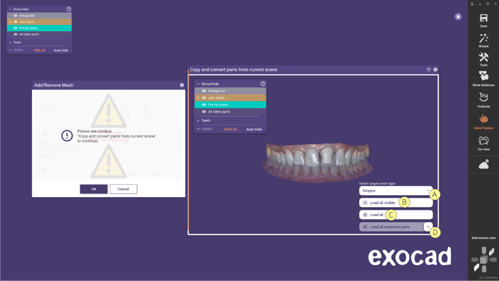
- The following window will open and you can choose from:
- [A] Select target mesh type - Choose the type of mesh you will load.
- [B] Load all visible - Load all visible parts from the loaded scene into the current scene. Use the Group menu to show/hide a specific part.
- [C] Load all - Load all existing parts, including anatomic parts from the loaded scene into the current scene.
- [D] Load all anatomic parts - Load all the anatomic parts from the scene.
- [A] Select target mesh type - Choose the type of mesh you will load.
Generating a Plane
By clicking Generate Plane [3], you can generate a plane, e.g. to visualize the occlusal plane. This button is only available if you select Antagonist as mesh type. You can position the plane using the mesh placement option.
Remove Meshes
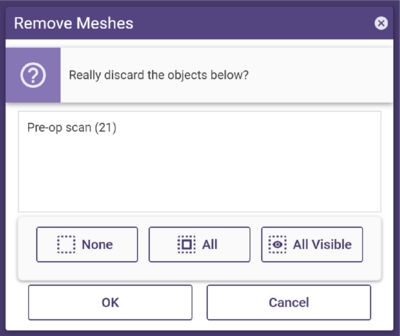
Step 1: Click Remove object(s). This opens the Remove meshes window. It lists all existing meshes of the currently selected mesh type.
Step 2: Check the checkboxes for meshes you want to delete.
Step 3: Click OK.
Mesh Placement Options
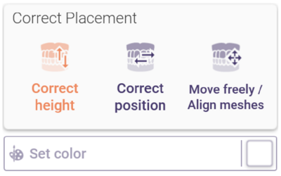
The Correct Placement section of the Add/Remove Mesh window shows mesh placement options. Which options are available depending on the type of mesh you have loaded.
- Correct height - Change the mesh’s height position along the z-axis by dragging it up/down.
- Correct position - Change the mesh’s position in x/y direction by dragging it.
- Move freely- Move the mesh freely by dragging it. Hold CTRL and drag to rotate the mesh.
- Set color- Define the mesh’s color (color selection via Choose color button).
Check Allow resizing to allow scaling the mesh. To scale the mesh, hold SHIFT and drag the mouse in the desired scaling
direction, indicated by a green arrow. To perform direction-based scaling, hold CTRL and SHIFT. Although this option is
available by default, you cannot actually scale all mesh types.
By clicking Show viewer axes, you can visualize the so-called scene coordinate system. Note that this does not necessarily
represent the scan coordinate system.
If you have loaded an antagonist mesh, the Correct Placement section appears, and you can move the mesh up or down along the z-axis with a specific step size. Define the step size by using the slider or typing in a value, and move the mesh by clicking Up/Down.
