Contents
Merge and Save Restoration
The last step in the wizard is the "Merging", which will:
- Combine (merge) all the individual elements you designed (copings, connectors, etc) into one or more meshes suitable for milling or laser melting. For each physical element you plan to produce, one mesh will be created.
- Save those meshes in STL format, with a _cad.stl file extension
- Write additional information (preparation margin, insertion axes, and much more) into the .constructionInfo file, which will be read by supported CAM applications
The saved files (.STL+.constructionInfo) will be located inside the respective project directory (the same one that opens when you use the 'Open in explorer' button in the DentalDB).
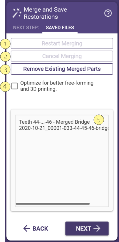
Merging and saving will start as soon as the dialog opens. The progress indicator shows the progress. You can stop the merging process with Cancel Merging [2], or restart it with Restart Merging [1]. Once the merging and saving has finished, the resulting output files will be displayed in the box [5]. You can use drag & drop operations here: e.g. you can drag and drop files directly from the box [5] into a directory of your choice, onto your CAM software, in an email composition window, or on an FTP server.
Once the merging is completed, the wizard is complete, and you cannot go back to any step. However, it's easy to reverse the process by clicking Remove Existing Merged Parts [3]. This will allow you to
- Change the "Optimize" Setting
- Re-enter wizard/expert mode to change or adjust any available wizard or expert mode setting (see "Expert Mode" for more explanation).
There is only one option in merging Optimize for better free-forming and 3D printing [4] (see explanation below). To switch to 3D printing optimization once you already have saved output files for milling, click Remove Existing Merged Parts [3], then Restart Merging [2].
Understanding the difference between output for milling and 3D printing
If your constructions are to be produced using 3D printing, as selective laser melting (SLM, often incorrectly referred to as "laser sintering"), the output data must be a "watertight" mesh with certain specific characteristics:
- No holes or open edges; completely interconnected mesh
- No inner surfaces or self-intersections
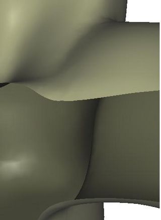
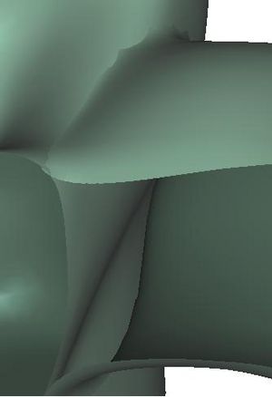
The figure above shows a sectional view of the junction between connector and pontic, with 3D printing (left) and without 3D printing optimization (right).
For milling, it is not mandatory that these special requirements are met. The post-processing for 3D printing involves time-consuming calculations, which is why the 3D printing optimizations (controlled by checkbox [4]) are only performed by default if a laser-melted material is selected in the DentalDB.
- If checkbox [4] is unchecked, resulting bridges cannot be produced using 3D printing
- If checkbox [4] is checked, the resulting output is still suitable for milling
| Even if not using 3D printing for production, it is helpful to enable the optimization for 3D printing, if you plan to perform additional freeforming on the finished construction. |
| You can also set to default the process of "optimize for free-forming and 3D printing". In the DentalCAD application, in the main toolbar click 'Tools' -> 'Settings' -> and check the 'Always optimize for free-forming and 3D printing' checkbox. |
Click 'Finish' to close the wizard. You're done now, you may close the CAD window and proceed to the next job. Alternatively, you can still perform additional modifications on the construction by closing the wizard and using the context menu. See section "Changing a finished reconstruction" for details.
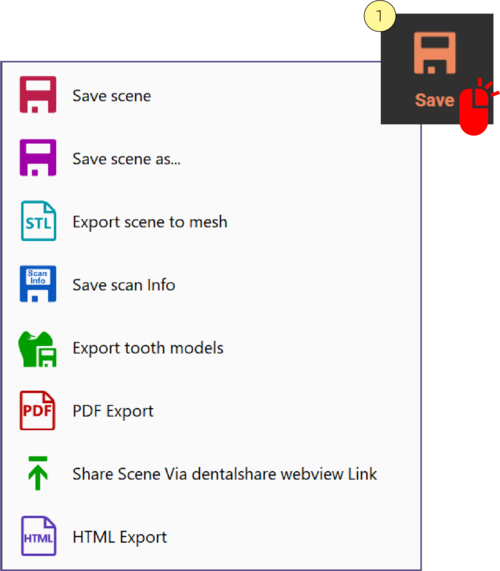
Save
Click to save a scene file representing the current design state in the project folder. By default, the scene file’s name is <ProjectName>.dentalCAD.
Right-clicking [1] the Save button shows the sub selections below:
- Save scene-Saves the current state of the CAD process in a "scene file" in the project folder
- Save scene as - You can rename the scene file, select another directory, and select a different file type in an explorer window.
- Export scene to mesh- Saves the visible objects as STL files to the project directory. Use the Group Selector to include/exclude objects to be exported.
- Save scan info- Save the scan information to a file. The following information will be saved: Per tooth: tooth number, tooth color, reconstruction type, preparation margin, and corresponding points (if you have already defined a margin for that tooth), name of the scan data file Per project: project name, project directory, details about scan data files (e.g. file name, file hash), transformation matrix.
- PDF export -Saves the visible objects as a PDF file, which can be viewed, rotated, and commented in Adobe Reader (version 4.3 or above). Use the Group Selector to include/exclude objects to be exported.
- Export tooth models-Export all tooth models as OBJ files to the project directory.
- Share Scene Via dentalshare webview Link- Share your 3D preview using dentalshare.
- HTML Export- Share your 3D preview exporting the scene to a shareable HTML file.
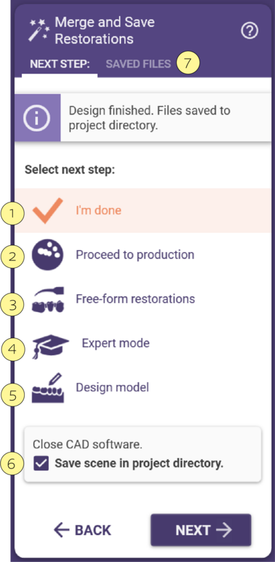
Next Steps
- I'm done [1] means that the design is complete. Simply close the DentalCAD window.
- Proceed to Production [2] Launch exocam CAM software (only visible if exocam license is present).
- Freeform Restorations [3] Opens a free-forming tool which can be used on the .stl. output. Confirm to save.
- Expert Mode [4] Shortcut to enter expert mode to make adjustments on the completed design (deletes the merged parts and requires re-merging).
- Design Model [5] If the Model Creator Module is installed, this will start the tool, and remember all the margins.
- Save Scene in Project Directory [6] Recommended if there is a chance that the design may be re-visited later.
- Saved files tab [7] combine (merge) all the individual elements you designed.
Screw Holes
When designing crowns/bridges on top of abutments, a screw hole can be applied to the superstructure. You can easily access the implant due to the screw hole in the superstructure.
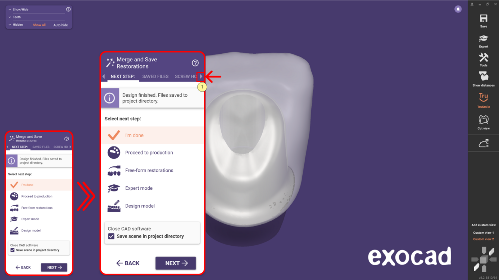 In the Merge and Save restorations step, click the arrow [1] to see the Screw hole option.
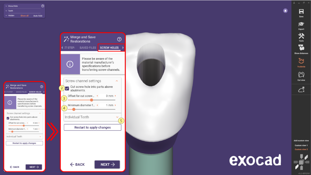 Selecting this option, check the box [2] Cut screw hole into parts above abutments to apply the cut. Use the slider [3] to adjust the additional radial offset for the cut of the screw hole through the superstructure parts that are cemented on top of the abutment. Note that after changing the parameter you must restart the merging.
Adjust the value [4] to keep a minimum diameter of the screw hole. The software will try to preserve this minimum diameter for the hole. Pay attention that due to the complexity of the screw channel shapes, this is only a heuristically value and it is recommended to use significantly larger values than required. Hint: Set the Offset [3] slider to a very small negative value to get this diameter as a result. Click [5] to expand the Individual teeth section, allowing you to select individual teeth to cut a hole.
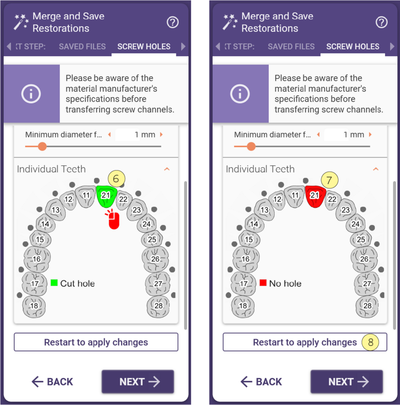
- If the tooth is marked green [6] it means that a hole will be cut. Click on the tooth to change the selection to No hole - red [7]. Click [8] to restart to apply changes.
