Contents
- 1 Using the Cut View feature
- 2 Interacting with the Cut View Plane in the main viewer
- 2.1 Mouse interaction with controls
- 2.2 After clicking the "Set by clicks" button in the cut view window...
- 2.3 After clicking "Follow mouse cursor" button in the cut view window...
- 2.4 Middle mouse button while control key is pressed on any clickable object:
- 2.5 Opening the Cut View from the "Show/Hide Groups" window
- 3 Cut View Window
- 4 Auto-Rotation modes
- 5 Miscellaneous
Using the Cut View feature
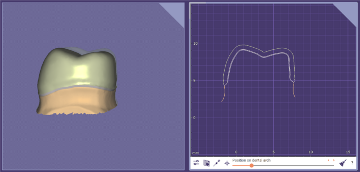 The 'Cut View' feature provides advanced methods for displaying sectional views of your design, and performing simple measurements.
Beyond what's shown in the video, there are also many hotkeys and special features, as documented below.
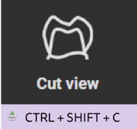
The Cut view button is displayed on the main toolbar.
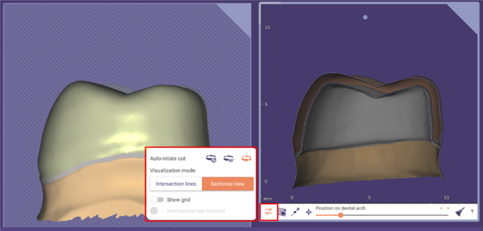
Clicking Cut settings expand the following additional functions:
Interacting with the Cut View Plane in the main viewer
Mouse interaction with controls
- The arrows in all directions at the cut rectangle edges move the cut arbitrarily.
- With Shift pressed, the movement is restricted the cut movement to the cut plane.
- The bent arrows in the middle of the cut edges rotate the cut along the corresponding circle.
- The controls are shown either by pressing ctrl or shift or by moving the mouse close to the border (rotation arrows in the middle of the edges, movement arrows everywhere else on the edge)
After clicking the "Set by clicks" button in the cut view window...
- The cut can be placed by two left clicks in the main viewer, the first one defines the center of the cut, the second one the direction and size.
- The placement procedure can be canceled by right clicking (without changing the view between pressing and releasing the right mouse button) the main viewer, by pressing the "Set by clicks" button again, or by pressing the escape key.
After clicking "Follow mouse cursor" button in the cut view window...
- When moving the mouse over the main viewer the center of the cut sticks to the mouse cursor until the button is pressed again or the left mouse button is pressed and released
- If Control key is not pressed, the cut is rotated along the tooth bow
- If shift is pressed, the cut is oriented along the surface normal
- If control is pressed, the cut is only moved, but not rotated
- Right-clicking the button toggles it into "locked mode". If it is activated the cut sticks to the mouse cursor even after clicking an object.
Middle mouse button while control key is pressed on any clickable object:
- Sets the center of the cut rectangle without changing the rotation center
Opening the Cut View from the "Show/Hide Groups" window
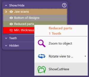
"Show cut here" in an entry's context menu defines a cut through the corresponding parts by right-clicking.
Cut View Window
Inside the cut viewer
- Mouse wheel without any additional keys pressed zooms in and out. Minimum and maximum zoom level is limited.
- Mouse wheel + Ctrl key moves the cut along the dental arch in small steps (if the position on dental arch slider isn't available, it moves the cut along the cut plane normal)
- Mouse wheel + Shift key moves the cut along the dental arch in larger steps
- Left + Right Mouse Buttons (pressed at the same time) pans the view
- Right mouse button behavior:
- clicking without moving the mouse opens a menu to zoom to specific objects
- dragging vertically while the button is pressed moves the cut along the cut plane normal
- dragging vertically while ctrl is pressed rotates the cut around the horizontal axis
- dragging horizontally while the button is pressed rotates the cut around the vertical axis (if auto rotation is disabled, the cut can be rotated around the plane normal by pressing the right mouse button near the cut view corners!)
- if ctrl is pressed the cut is rotated around the horizontal axis
- Middle bouse button centers the view on the click point
Measurement tool in the cut viewer
- Left-click and drag to position marker points (jumps intersection curve, if one is nearby).
- Control key + left click / drag to move without jumping to intersection curves.
- While the mouse is near a marker (circle around the dot), hitting Delete key will delete that marker.
- Clicking the right mouse button while moving a marker with the left mouse butten deletes the marker as well.
- End points are green if they are snapped to an intersection curve, yellow if they were placed outside the snapping radius or positioned while control was pressed. They change their color to red if they lost the object they were previously snapped to.
- The lengths between the two markers is only displayed if none of the markers is red.
- The markers and the arrow are also displayed in the main viewer in the color of the rectangle.
- When the 3D Measurement Tool (from "Tools->Measurement Tool") is open, it can be used in the cut view viewer as well, and the 2D measurement tool of the cut view is deactivated.
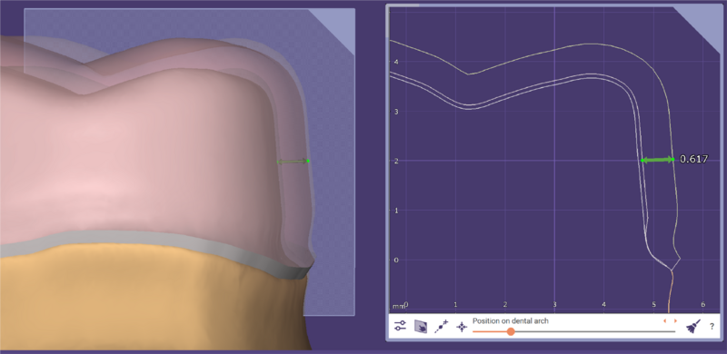
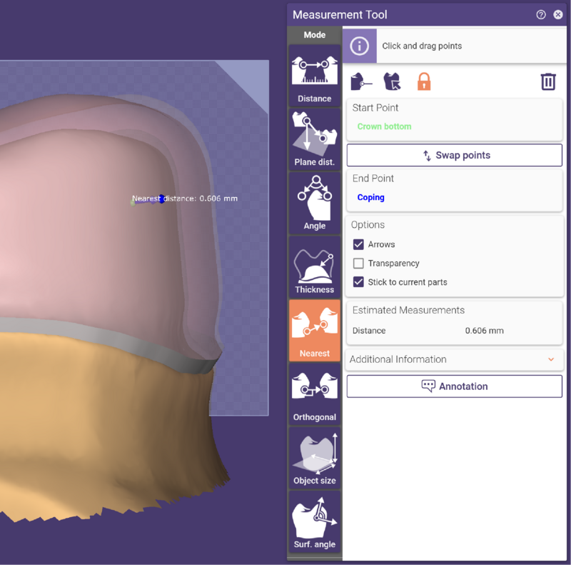
Warning: Use 2D measurements wisely, know the limitationsMeasuring a 3D situation in a 2D sectional view is an oversimplification, and such 2D measurements are prone to misinterpretation (as illustrated below). Especially consider this effect when checking minimum thicknesses or minimum clearances. We recommend to use 3D measurement (in Tools->Measurement tool) in such situations instead. Always keep in mind that the 2D measurement tool only measures distances in the particular cut plane you have chosen, and not the shortest distance between two surfaces. Example for the limitations of a 2D measurementThe picture below shows a measurement in 2D of an offset coping. One might be tempted to interpret the measurement of 0.617mm as the thickness of the coping. This is wrong, as the direct line between the first measurement point (on the inside of the coping) and the point closest to it on the outside of the coping does not necessarily lie in the currently chosen 2D cut plane. In the picture below, you can see the correct measurement in 3D. The first measurement point, on the inside of the coping, is the same as in the example above, but the point closest to it on the outside doesn't lie within the plane that was chosen as cut view plane. |
Auto-Rotation modes
In the options dialog, different rotation modes are available:
- Disabled: The cut doesn't rotate if the main viewer view changes
- Discrete: The cut only rotates in 90° steps such that the corner marker is in the top-right most corner of the cut in the main viewer
- Smooth: The cut rotates in some way smoothly (except when looking at the cut rectangle from the side)
Miscellaneous
- The size of the cut view window can be changed by grabbing and dragging the upper left corner of the border of the cut view window.
