|
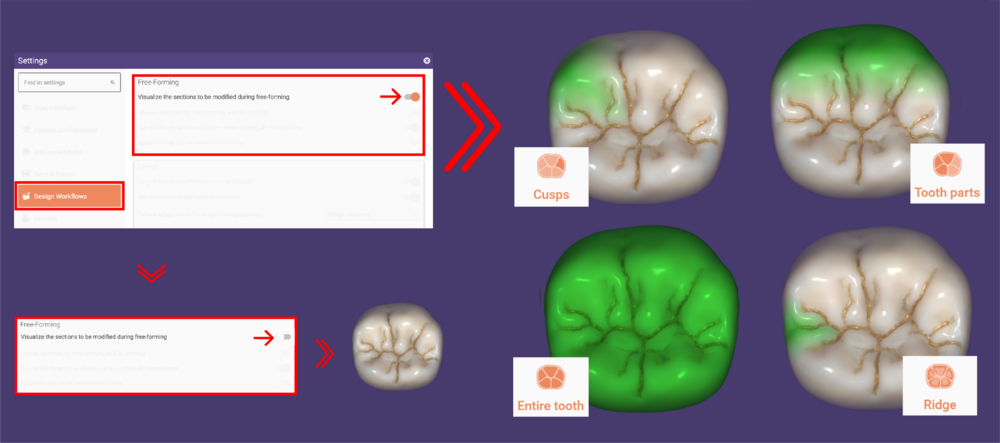
Use the Presets buttons [1]-[4] to change the area that you're editing:
- Cusps [1] edits individual cusps. Note that this only works properly for restorations based on model teeth (anatomic crowns/copings, anatomic inlays, etc). For offset copings or waxups, the software cannot know the location of the cusp.
- Tooth parts [2] edit the mesial, distal, buccal, or lingual side, wherever you click on. Useful e.g. for adjusting approximal contacts.
- Entire tooth [3] edits the entire tooth.
- Ridge [4] is for fine-tuning of ridges/bulges.
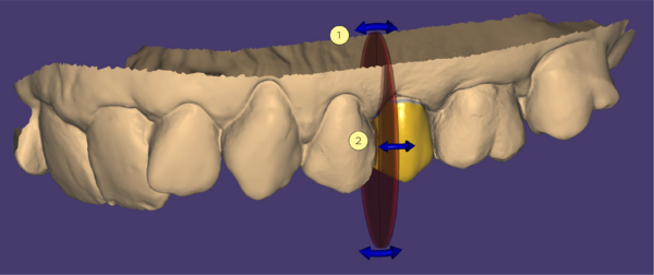
 | Useful hotkeys are available in the "Entire tooth" mode. Hold CTRL to switch to rotation, SHIFT to switch to scaling. This way, you can rotate or scale the tooth while it remains attached to the preparation margin. As always, the software will remind you of the available hotkeys if you move the mouse over the respective button [3]. |
To restrict the transformations to occlusal direction, check Occlusal Only [5]. To hold either the cusp tips [6] or the equator [7] fixed, activate the corresponding buttons (note: this only works for restorations based on model teeth).
 | You can also drag and drop the bottom of a pontic when in "Anatomic" forming mode. |
| A useful example of how you can take advantage of this option: To create deeper or flatter fissures, switch to Entire tooth [3], then check Lock cusps tips [6]. Now, you can simply drag and drop fissures to make them more or less pronounced, without overly changing the rest of the tooth shape. |
- Click Cut all intersections [8] to cut all intersections with the antagonist, adjacents, and, for pontics/waxups, to the gingiva.
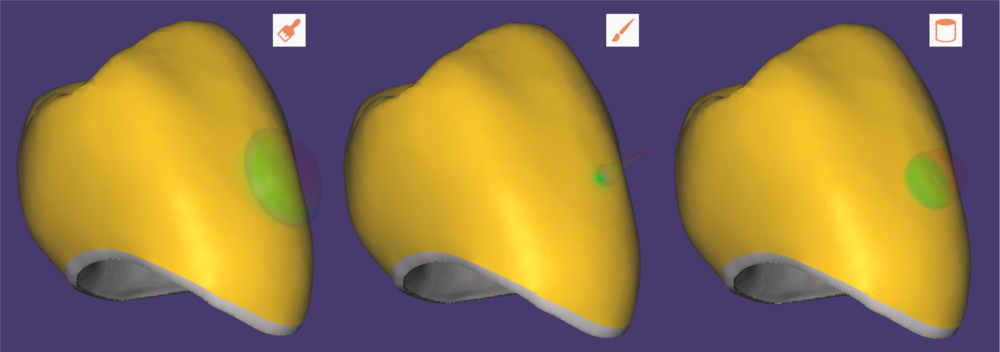
- During the anatomic free-forming, the affected parts of the design will be visualized. This option is enabled by default and highlights in green the affected parts. Under settings, you can uncheck Visualize the sections to be modified during free forming as shown below. Don't forget to restart the software to apply the new settings.
By expanding the Paint & Pull [9], you can access two options allowing you to restrict the movement in certain ways.
Paint areas that you wish to move by brush in Paint moving parts [1].
Then, click on Pull moving parts [6] to move, pull, deform, scale, or rotate the parts of the surface that you have painted.
Green Brush size [2] marks areas that can be pulled by mouse.
Yellow Elastic area [3] marks elastic band that is automatically painted around the green area.
To clear all markings, click Reset [5] .
You can pull moving parts by activating Pull moving parts [2]. Note that the Invert button [4 ]can only be activated in advanced editing mode. You can access advanced paint & pull features by clicking on Advanced Editing [7].
In advanced editing mode, you can select between Moving areas [7], Elastic Areas [8 ], and Static areas [9] by activating one of the corresponding buttons and dragging your mouse.
Define the brush size using the Brush size slider [10].
To invert the function of the painted areas, click Invert [11].
To clear all markings, click Reset [12].
You can pull moving parts by activating Pull moving parts [13].
Cut all intersections to the antagonist, adjacents, and basal for pontics/waxupds by clicking the corresponding button [14].
Advanced editing example
|
Green surface will always move with mouse.
Yellow surface will behave like an elastic material.
Blue surface will always stay fixed.
|
| While painting areas, you can also use hotkeys CTRL or SHIFT to adjust the brush mode. Also, while moving the surface, you can use hotkeys CTRL or SHIFT to rotate or scale the moving surface parts. |
Free
Click the 'Free' tab to switch to the "Virtual wax knife", which allows you to add or remove material. You can toggle between Add/Remove [9] material and Smooth/Flatten [10] or Adapt [11].
Add/Remove
To add or remove material, click on the tooth and hold Add/Remove [9]. The longer you hold it, the more material will be added.
| Hold <SHIFT> to remove material |
Smooth/Flatten
Activate Smooth/Flatten [10], click and hold the mouse button on the parts you'd like to smooth.
|
- Hold SHIFT to flatten (super-smoothing)
- Hold CTRL for a more shape-preserving smoothing
- While in Add/Remove mode, hold CTRL+SHIFT to smooth/flatten without having to activate the Smooth/Flatten button
|
Adjusting the Brush
Using the slider Strength [12], you can adjust the speed at which material is added or removed while you hold the mouse button (or the amount of smoothing when in "Smooth/Flatten" mode). The slider Brush size [13] controls the brush size, that is the affected area around the mouse pointer.
Type [14]: There are 3 types of brush styles to select from:
- Round ball (default)
- Pointed, like the point of a knife
- Flat end of cylinder
| You can also use the smoothing option to remove certain artifacts (e.g. due to bad scan data when doing digital copy milling). |
Adapt
In the Free tab, you can click the button Adapt [11] to access further free-forming options: Automatically adapt the chewing surface to the antagonist, contacts to the adjacent teeth, and pontics to the gingiva. Note that the Adapt button is not
available in every free-forming step.
There are two basic types of adaptation: Occlusion (You can choose between static or dynamic occlusion) and Approximal.
Select the desired adaptation type by using the corresponding expander icons [4]. If you design a pontic/waxup, a fourth
expander button Basal is available to adapt pontics/waxups to the gingiva . If preconditions for an adaptation are not fulfilled, it will not be performed.
Basal [1]
The slider [5] controls the distance to the gingiva after the adaptation:
- A negative value means that the pontic/waxup will intersect the gingiva scan (that is, the physical pontic will apply pressure on the gingiva).
- A positive value means that there will be a gap between the gingiva and pontic/waxup.
- Zero (default) means that the pontic/waxup will be in direct contact with the gingiva.
Check Pull down to gingiva [6] if the gingiva is so low that the pontic/waxup does not intersect it. This will pull down the pontic/waxup towards the gingiva during the adaptation. Alternatively, you can pull the pontic/waxup down to the gingiva manually by either clicking and dragging the mouse near the pontic bottom surface or by using the tools under the Anat. tab.
- Click Basal [1] to perform the adaptation individualy.
When designing reduced pontics, the free-forming step will appear twice, before and after the reduction. You can perform the pontic adaptation on the full anatomy or the reduced shape. To ensure the exact distance value is respected in the final restoration, perform the adaptation after the reduction.
Static occlusion [2]
To cut intersections according to the selected adaptation type, click Static occlusion [2].
- You can choose between Direct cut adaptation [8], to make a regular cut or, shape-preserving adaptation [9], which will try to preserve the tooth morphology. For certain cases, this button is deactivated (e.g. for offset copings, offset inlays, veneers, waxups) and shape-preserving adaptation cannot be performed.
- You can define a distance from the designed anatomy to the antagonist using the Desired distance slider [7]. A negative value will create an intersection.
- If you check Exclude selected parts [10], a window appears with brush tool functions. Using these functions, you can paint areas on the model teeth which will be excluded from adaptation.
Dynamic occlusion [D]
- If the virtual articulation has been performed, Dynamic occlusion [D] is available by default.
- If you have restorations in both jaws, you can select the jaw to adapt using the Upper [1] Lower [2] or Both [3]. If you select both, use option [4] to adapt the reconstructions of both upper and upper jaw in sequence. Toggle the switch to set the jaw to be adapted first. Hint: Avoid using this option for opposing reconstructions! In such cases, you must review and adjust the articulator-influencing teeth manually.
- Click Cut all intersections [8] to cut all intersections with the antagonist, adjacents, and, for pontics/waxups, to the gingiva or Dynamic occlusion [D] to adjust only this parameter.
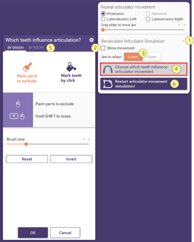
- Expanding the Recalculate Articulator Simulation [1] you can Choose which teeth influence articulator movement [4] opening the window [5]. Here, you can select which teeth influence the articulation, this page has further information about this topic. Select the Show movement [2] checkbox if you would like to visualize the movement simulation. You can choose the Jaw to adapt [3] and clicking Restart the articulator movement [6]will apply the changes without the need to open the Articulator window.
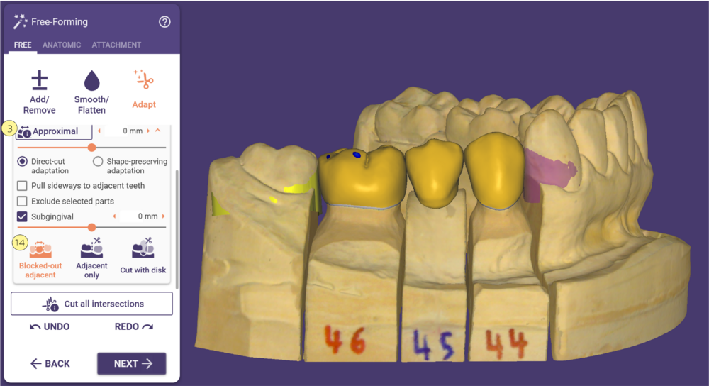
Approximal [3]
- The option Blocked-out adjacent [14] will temporarily block out the scanned approximal neighbors relative to the tooth’s insertion direction, to allow a collision-free fitting of the restoration.
- Click Approximal [3] to adjust according to this option.
Adjacent only
- If there is a gap between a restoration and adjacent(s), you can check Pull sideways to adjacent teeth [11] to move the restoration border(s) sideways so that they are in contact with the adjacent teeth. If checked, the slider Intrusion before cut [12] appears, allowing you to define intrusions with the adjacent teeth. These intrusions will be applied before intersections are cut away.
- Exclude selected parts [10]: a window appears with brush tool functions. Using these functions, you can
paint areas on the model teeth that will be excluded from adaptation.
Cut with disk
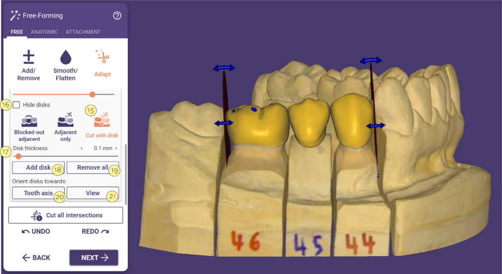
- When activating the checkbox Cut with Disk[15], DentalCAD will place one or more disk(s) at the mesial/distal ends of a bridge or single tooth constructions.
- Click [16] to hide disks. You can use the disk(s) to cut away material. The following functions appear upon activating the checkbox:
- Disk Thickness [17] : Slider to adjust the thickness of the disk(s). Useful if you want to cut away material between two constructions.
- Add Disk [18]: Add another disk to the construction. Place the disk by left-clicking the desired position.
- Remove all [19] : Remove all disks.
- Tooth Axis [20], View [21]: Orients the disk(s) towards the tooth axis or the current view.
After you have placed the disk(s) at the desired position, you can use the following buttons to cut away material from the construction(s), click Approximal [3] selecting direct cut or shape-preserving adaptation.
 You can use the blue rotation handles [1] and
[2] to further adjust the position of the disk by left-clicking and dragging.
You can use the blue rotation handles [1] and
[2] to further adjust the position of the disk by left-clicking and dragging.
|
SHORTCUTS
- Left-click + drag: Move the disk.
- Left-click + right-click on disk: Remove the disk. Alternatively, you can hover your mouse over the disk and press the DEL key to remove a disk.
- CTRL + left-click: Rotate the disk freely.
- SHIFT + left-click: Stick the disk to a contact point on the reconstruction.
- CTRL + SHIFT + left-click: Stick the disk to a contact point on the reconstruction and align it to the surface. Note: While stuck to a contact point, the disk is moved so that the contact point is always included in one of the disk’s sides (or the plane defined by that side).
- Left-click + drag on contact point: Move the contact point.
- Hover over disk + DEL: Unstick a disk from a contact point. Alternatively, left-click and drag the disk until it unsticks from the control point.
|
Attachment
In the "ATT." tab, you can add or remove (cut out) library parts (such as attachments or bolts), or even certain STLs loaded from file, to your restoration.
- To add/subtract attachment shapes, select Add [1] or Subtract [2].
- Select the attachment library and type using the drop-down menus [3] and [4] .
- Activate Move [5] to move the shape, Rotate [6] to rotate it, and Scale [7] to scale it. While in Move mode, use SHIFT to move along the insertion direction, CTRL to rotate around the insertion direction, and CTRL+SHIFT to rotate the attachment freely. Some attachments cannot be rotated and/or scaled depending on the attachment library settings.
You can select the Insertion Direction [8] for the attachment as
- from the Top as viewed from the scan data orientation,
- from the current View direction, or
- perpendicular to the restoration Surface.
Cut on gingiva [9] will automatically cut the attachment to the scan (if the slider value is 0), or to a fixed distance defined by the slider. Negative distance values mean intersection with the scan.
Click Apply [10] to add/remove the attachment. Click Unload [11] to clear the attachment selection.
Alternatively, you can drag&drop an STL attachment file into the main view, copy&paste an STL attachment file into the main view, or drag the path to an STL attachment file into the main view.
Text Attachments
You can add text attachments to a restoration, as shown:
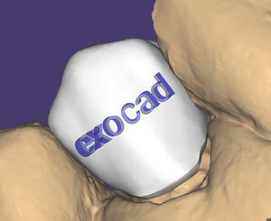
To add a text attachment, select Text in the Library drop-down list [1]. By default, the attachment text is the filename of the current scene. You can edit the text in the text window [2]. Clicking the arrow icon next to the textbox opens a new window where you can select a font, format your text attachment bold and/or italic, and choose from a selection of supported symbols. Confirm your font selection by clicking OK.
Move the text attachment to the desired position on the restoration. Activate Rotate [3] to rotate the text. Click the desired position on the restoration to set the text attachment. Once positioned, you can still drag and drop the text attachment. By clicking Unload [6], you detach the text again from the restoration.
Using the slider Thickness [4], you can change the text depth, with Size [5] you can define the text size.
Click Apply [7] to adapt the text attachment to the restoration.
|
|