Post and Core


The Post and Core feature is available for early prototype testing upon request. It requires a separate module activation. Please contact your reseller to enable it.

- In DentalDB, start by defining the work type [1]. Then, you need to select the Material [2] for the restoration [A] and the Post and Core material [B]. Under “Implant- based?” you need to select the Post and core [3] option and as an additional Scan, choose to use the Scan Body [C] or Don’t use Scan Body [D]. Click OK to continue.

- Select Design [5] to start DentalCAD.

- If you selected to use the Scan Body [C], in the first Wizard step you need to detect the Marker Position.
| If you are using a Scan Body for your Post&Core case, an extra scan must be used for this Scan Body. The matching process for detecting the marker position must not be used in combination with a scan comprising the patient’s teeth. The extra scan used for matching must be limited to the the scan body only. |

- If you selected Don’t use Scan Body [D], in the first Wizard step you start by detecting the Inner Margin Line. This is the second step if you select to use the Scan Body [C].

- After defining the inner margin line, you can place the model tooth as usual.

- Then you need to define the Insertion direction of the post.

- Clicking next, you can adjust the Post Bottom [9]. This part of the construction and the parameters involved influence the fitting. Check this page for detailed information.

- In the Design Core [10] step, you can adjust the core.


- Start by defining the abutment core minimum angle with the slider [11].
- Define the space between the abutment core and the underlying anatomy using the slider [12]. Activate the checkbox [13] to automatically adapt the occlusal area keeping the space defined in [12]. Click [14] to Apply the “Spacing” value defined to the control points, it can either increase or reduce the abutment core size. Using [15] apply parameters only by reducing the abutment core size. Hold SHIFT + CTRL while clicking to reset the shape to default.
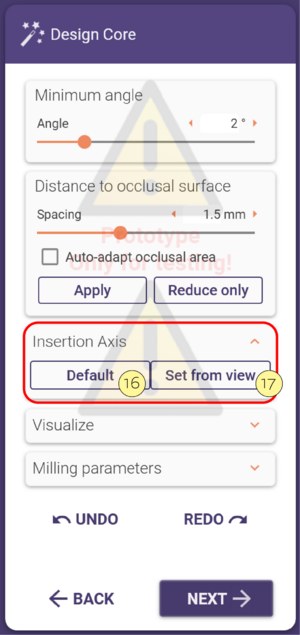
- In the Insertion Axis section, select Default [16] to keep the insertion direction or choose Set from view [17] to define another one.
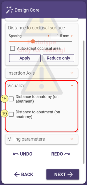
- With activating the checkbox Distance to anatomy (on abutment core) [18], you can visualize the distance of the anatomy to the abutment core, the visualization is displayed on the abutment core. The visualization is color-coded from red (low distance), to blue (high distance). You can also have a measurement of Distance to the abutment core (on anatomy) [19] displayed on the anatomy.
core.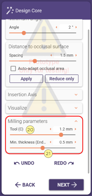
- In the milling parameters section, the slider [20] will select the diameter of the tool that will be used to mill the crown/coping that will be fitted on the abutment core. Use slider [21] to adjust the minimum thickness of the inner endo crown


- Clicking next you will be able to Free-form [22] the core. Use the Freeforming tools as usual.

- Finally, you will reach the Merge and Save Restorations step. Here you can decide what to select in the next step. Choose Design suprastructure now [24] to directly design the part that fits on the abutment core.
