Designing the inside of the crown


This step covers the design of the inside of the crown/inlay – the part that will be in contact with the preparation. This part of the construction, and the parameters involved, are crucial for proper fitting. In case you are not happy with the fitting of the produced part, it's here where you should look for possible parameter changes.
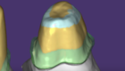
The cement gap
 The cement gap and additional spacing options can be set in the first tab of the 'Cement Gap' dialog. Cement gap areas are displayed in yellow on the preparation, areas without cement gap are displayed in green.
Cement gap options:
- Edit yellow/green areas by selecting the corresponding brush icon [1] and drawing on the preparation. To draw, hold the left mouse button and drag. To invert the brush functionality, hold SHIFT.
- Set the cement gap using the Gap slider [2].
- Click Add another zone [3] to add a third area in another color on the preparation. You can edit this area using the corresponding brush icon, as explained above. There is also a slider available to define the third zone’s width.
- You can add spacing in axial direction that will be applied everywhere using the slider Axial [4]. To add horizontal spacing perpendicular to the axial direction, use the slider Radial [5]. By default, these sliders are locked (indicated by the active lock icon), which means that you cannot move them individually. Click the lock icon to deactivate this behavior.
Designing the crown border
The second tab of the 'Crown Bottoms' dialog gives you access to parameters that define the shape of the crown border. The graphic illustrates the meaning of the sliders [1-5].

Horizontal [1] defines the horizontal crown border width. Typically, material properties enforce certain limits here; e.g. for Zirconia a common minimum value is 0.2mm.
Angled [2] defines the length of the angled part of the border. This may commonly be set to zero.
Angle [3] defines the angle of the angled part.
Vertical [4] defines an additional vertical border. Commonly this is also set to zero.
Below margin [5] defines an absolute offset of all the drawn margin points (the left side of line 1) in the insertion direction.
Advanced
The third tab in the 'Crown Bottoms' dialog gives you access to undercut-related options and milling parameters.

Undercuts in the preparation are blocked out by default, unless you specifically choose not to do so by checking Don't block out undercuts [1].
A certain (small) angle may be applied for blocking out undercuts by sliding Angle [2]. By default, a value of zero is used, meaning that undercuts are blocked out "straight down".
The slider Size [3] defines an "untouchable zone" around the preparation margin, where the crown is never blocked out, even if it should be (due to undercuts being present above).
We will further illustrate the effect of this option with an example. Consider the two images below (for this tooth, we have intentionally set an incorrect insertion axis to illustrate the problem).


The graphic on the left shows the behavior with 'Don't block out undercuts' set to 1mm. Observe how the upper part is blocked out, but as soon as the untouchable zone is reached, the crown bottom will go back to the preparation (note that it is not possible to produce this kind of restoration with 3-axis milling).
The graphic on the right shows the behavior with 'Don't block out undercuts' set to zero. As you can see, the crown will not be in contact with the preparation around the margin.
In both cases, the result will be not ideal and the restoration will need manual work (either manual milling, or adding ceramic) for a proper fit. It is up to the operator to decide which option may be better in the particular clinical case.
|
In the third tab of the 'Crown Bottoms' dialog, you can also change the parameter for tool diameter compensation. If you have selected a material that is to be milled, the checkbox Anticipate milling [4] is checked by default. Under Diameter [5], you can choose the diameter of the tool to be used for milling. It is beneficial to choose a value slightly higher than the diameter of the actual tool you're using, e.g. chose 1.2mm when milling with a 1mm tool.
Bullnose/flat tool [6]: DentalCAD supports tool compensation for both round and non-round milling burs, called bullnose tools. Unchecking enables round burr tooling compensation, while checked means bullnose tool compensation. In both cases, DentalCAD will show you the ideal tool-compensated result. If this checkbox is active, undercuts will always be blocked out (checkbox Don’t block out undercuts is deactivated).
You can adjust Tool tip flat percentage [7] to define your bullnose tool. 0% value means a round burr, while 100% means a true flat-end burr is being used.
| Consider the diameter of the smallest tool used. The diameter of the roughing tool is of no interest here. |
Note that depending on your software configuration, additional options ('Bullnose/Flat tool', 'Tool tip flat percentage' may be visible in this screen. For details about these options, please see our video documentation.
To visualize remaining undercuts (e.g. due to usage of 'Don't block out zone near prepline'), click Show undercuts [8]. The software will block out undercuts that are up to about 1mm deep.
Any parameters you change in this screen will not be applied in real time, as these are computing-intensive operations. Click Apply [9] to see the effect of your changes.
When done, click 'Next' to proceed to the next step.