Contents
- 1 Overview
- 2 Hotkeys
- 3 Choosing the profile
- 4 Bar Profile Parameters
- 5 Wizard: Bar Design
- 6 Creating custom profiles
- 7 The planes
- 8 Using the control points
- 9 Setting the insertion axis of the bar
- 10 The effect of the insertion axis on pillar shape
- 11 Extending the bar profile library
- 12 Designing superstructures over bars
Overview
The Bar Module allows the user to fabricate bar-type prostheses ranging from prepared teeth crowns and bridges to implant supported screw retained or custom abutments. This module allows multiple bar shapes in an arch and customizable bar profiles. It also includes the ability for attachment placement and retention pillars.
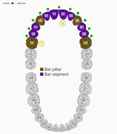
To begin, the dental database must be correctly completed. The Bar pillars [1] indicate where the abutments/implants are located, the Bar segments [2] are the connectors between the pillars.
Hotkeys
| Mouse interactions & hotkeys for bar module |
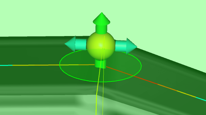
You can move the control points (the small balls) by dragging them with the left mouse button. You can also drag the arrows for restricted movement in one direction.
| Control+Click | Add Control Point |
| Drag Point + Right click | Remove control point |
| Shift+Drag | Move point and it's neighbors |
| Control+Drag | Move point and it's further neighbors |
| Control+Shift+Drag | Move ALL points (using insertion plane) |
| Click on arrow | Toggle automatic placement of control point. Hold <Shift>, <Ctrl> or both to extend toggle-range. |
Choosing the profile
When the bar design screen is open, a profile selection window will show.
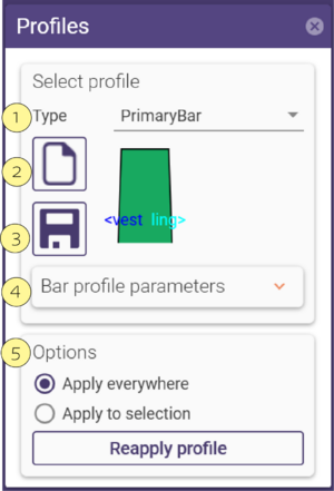
Select the desired profile from the Type [1] drop-down box.
By default, the newly selected profile will be applied to the entire bar. By selecting the Apply to selection radio button, you can apply new profile choices only to the currently selected bar segment (marked by purple with yellow outlines). To select a specific segment, simply click on it. You can change profile parameters by unfolding the Bar Profile Parameters expander.
Once the initial steps have been completed and you have reached the Wizard window Bar Design the Profiles window will appear.
In the Profiles window you will see the Select profile section. Here you can choose the Type [1] of bar profile from the pulldown.
In the Bar Profile parameters [4] pulldown you can adjust many sections of the bar in various ways to suit your desired shape. If this shape is one that you would like to use again, you can click Save [3]. This save will allow you to rename your new bar profile and it will be accessible in the Type [1] pulldown for future use. To access this click Folder [2]. The Options [5] section will allow you to apply a particular profile to a selection or segment of the bar or to the whole bar. If you made a mistake you can re-apply the profile.
If you would like to create a custom profile please see: Extending the bar profile library
| A bar segment is indicated by purple color with yellow outlines. |
Bar Profile Parameters
Choosing different profile type, you have different options within the section Bar profile parameters [4] as shown:
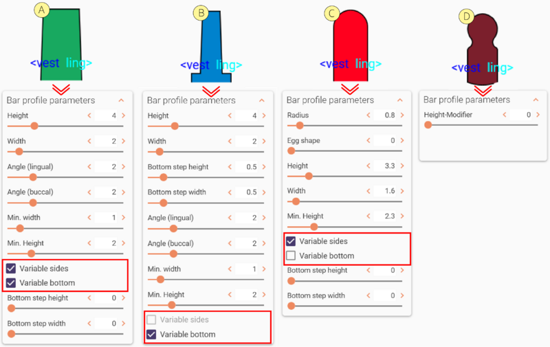 As you can see, the profile can have different colors, Green [A], Blue [B], Red [C], and Dark Red [D]. Each color means different parameters available to perform changes.
- Green [A]: Allows to change "Variable Sides" and "Variable Bottom" by checking the selection boxes.
- Blue [B]: This profile has only ‘’Variable Bottom’’.
- Red [C]: This profile has only ‘’Variable sides’’.
- Dark Red [D]: This means the profile is fixed by XY points, not allowing any changes.
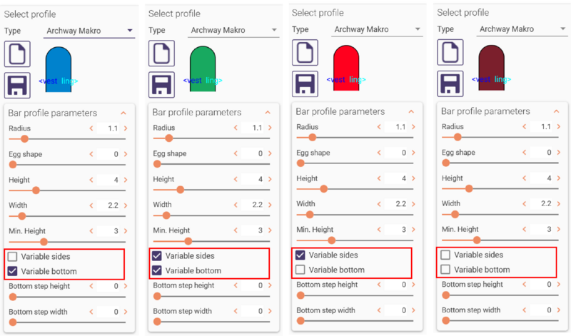
Some profiles allow you to check or uncheck variable sides and bottom which will change the initially selected color. This is not available to all pre-sets, some are limited. You can find an example below:
| There are bar systems known by specific nomenclature or trade names. Please note that exocad is a pure technology provider and the integration of third-party components (and its library names) is decided by the component supplier. |
Wizard: Bar Design
Here you will see 3 tabs: PROFILE, ADVANCED and ATT. (Attachments).
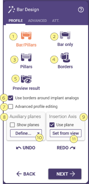
In the PROFILE tab there are many features:
Bars and Pillars [1]: Adjustment of bar and pillars simultaneously.
Bar only [2]: Adjustment of the bar only.
Pillars [3]: Adjustment of the pillars.
Borders [4]: Adjustment of the borders only.
[5] This allows you to preview the result of your changes made to the prosthesis.
[6] This box, once checked, allows you to use borders around the implants. This is to accommodate extra space of the papilla around the implant/tooth.
[7] This box, once checked, allows you to use the advanced profile editing. See section advanced profile editing.
Auxiliary Planes: Show planes [8] section Planes
Insertion Axis: Use plane [9] section: Insertion axis of the secondary frame that will fit over the bar. This axis can be changed by a view dependent setting of the model or can be viewed by having the check box checked.
Define [10] : this drop down will allow you to Set From View [11] Rotate the model to a desired position for your Path of Insertion, then click this button.
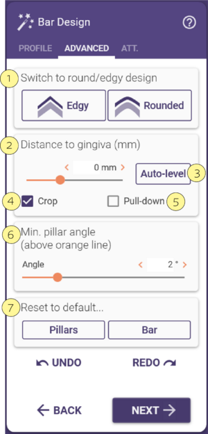
In the ADVANCED tab, there are other features:
Switch to Round/Edgy Design [1]: Adjustment of edgy or rounded profile of the bar.
Distance to Gingiva(mm) [2]: Distance slider in (mm)...... If you check the Crop [4] checkbox......... If you check the Pull-down [5] checkbox then......
Auto Level [3]: This maintains the height (size) of the bar after it has been adapted to the gingiva, as to avoid dips in the contour height or an unlevel surface of the top of the bar.
Min. Pillar Angle ( Above Orange Line ) [6] : Angle slider in degrees.
Reset to Default [7]: Pillars and Bar : You have the option to work on just the pillars or just the bar.
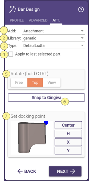
In the ATTachment tab, the following features are available:
- Add [1]: Add an attachment selection from the drop-down list. There are the following options:
- Attachment: 3D mesh to add to the construction.
- Bolted: 3D mesh to subtract.
- Visualizer: 3D mesh for visualization purposes only.
- Retention: 3D mesh to add to the construction in order to create retentions.
Library [2]: Select a name from the drop down list. You can find here a list of the available libraries.
Type [3]: Select a file type from the drop down list.
Apply to Last Selected Part [4]: If this option is selected, when you modify [1], [2] or [3] individually or simultaneously, it will apply automatically the changes to the last selected part placed.
Rotate [5]: This affects the rotational movement around the pivot point of an attachment. "Free" allows total freedom of movement in all directions. "Top" restricts the movement to orbital rotation on top of the bar. "View" is setting the rotation to the current view that you have moved the model ( Bar ) to on the screen. ( similar to a path of insertion in C & B )
Snap to Gingiva [6]: Left-clicking this tab will make the attachment adjust to the tissue surface.
Set Docking Point [7]: Center is the midpoint/center of the attachment preview (left click to apply dot); H is the height / X is the horizontal axis direction / Y is the occlusal axis direction.
Creating custom profiles
To create your own profile, you can use one of the already available profiles as template and change the parameters to reflect the desired shape. Then, click on Save.
| When you save the new bar profile file in the directory DentalCADApp\library\bar (using a name of your choice, but with extension .barProfile), the new profile will be included in the profile selection list the next time you start the software. |
To create profiles that are more radically different from the already available profiles, see section Extending the bar profile library below.
The planes
Planes help you during bar design. They serve as a reference, and can define the insertion axis.The planes are displayed when you activate the Show plane box in the first tab:
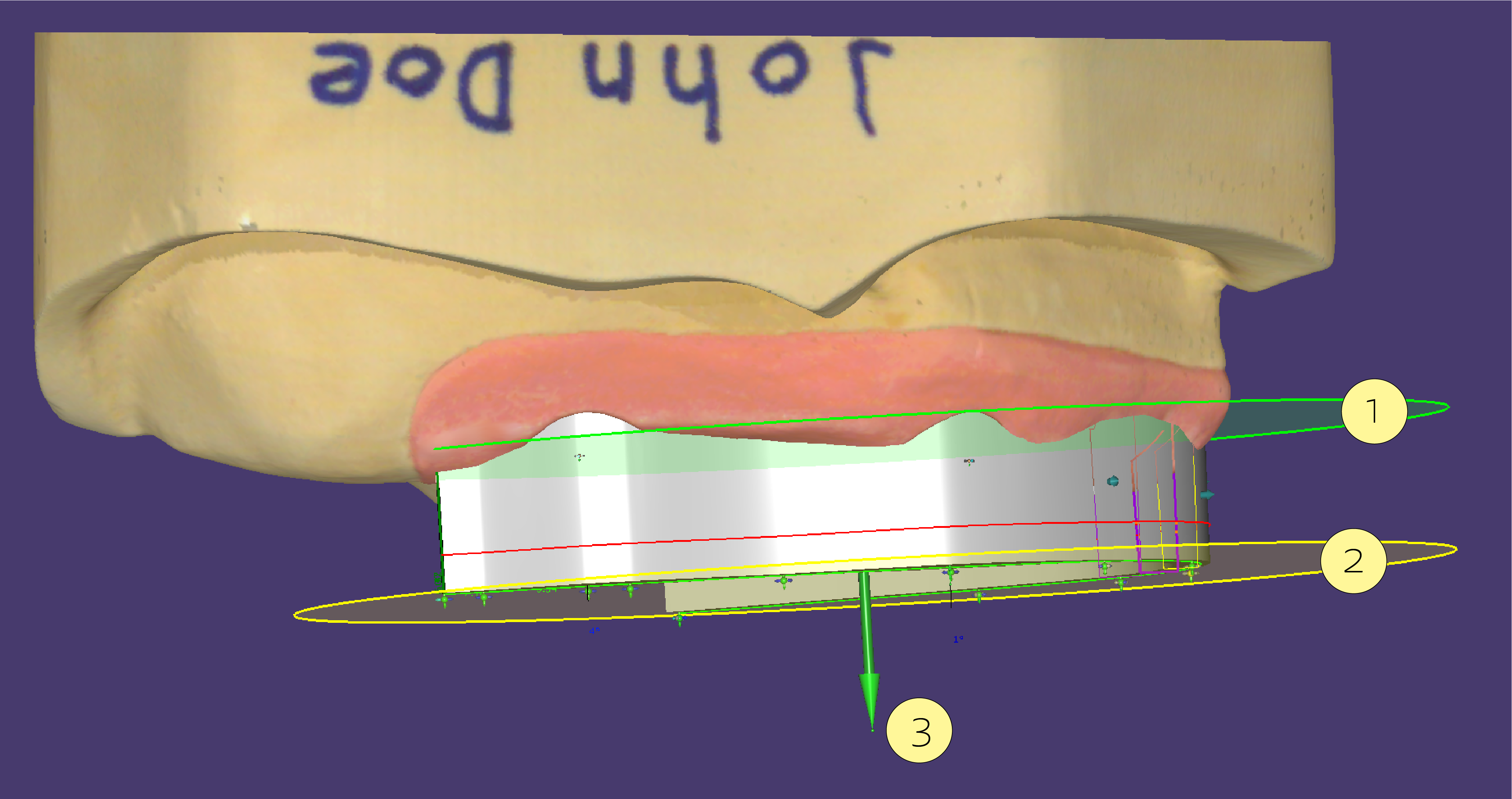
- The reference plane (green) [1]: This plane is typically used to define the top of the bar.
- The auxiliary plane (yellow) [2]: This plane is parallel to the reference plane, but positioned at the height of the currently selected control point. It helps you to see easily what the height difference between the currently selected control point and the reference plane is.
You can change the inclination of the planes by dragging the green ball [3]on top of the control arrow in the center of the plane. You can move the height of the reference plane to the height of a specific control point by double-clicking the control point (in other words - double-click the selected control point to reposition the green plane to the exact position of the yellow plane).
Here you can make the planes visible by having the checkbox checked.
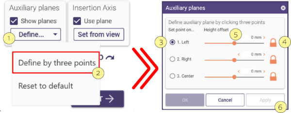
There also is the Define plane [1] pulldown:
Here you are able to reset the plane or click to define a plane by three points [2] and a height offset. In this case, a new window appears called Auxiliary planes [3].
Lock [4] to keep the same Heigh offset for left, right, and center.
Unlocking [4] allows changing individually with the sliders [5] the Height.Click Apply [6] when finished.
| Don't mix up the reference plane with the occlusal plane. Usually, you set the reference plane parallel to the occlusal plane but much lower. |
Using the control points
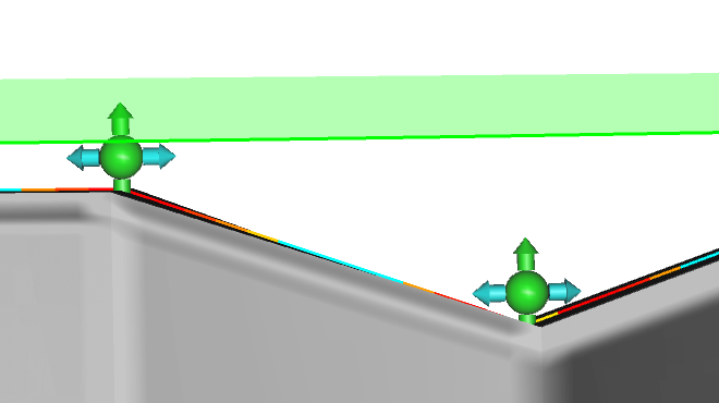
Control points can be snapped to each other (to keep them parallel to the reference plane), or to the reference plane itself (when the plane is visible).
By default, each control point can be moved independently of it's neighbors:
By clicking one of the cyan arrows, which point to it's neighbors, you can link the height of a control point to it's neighbor:
The fact that two control points have their height linked to each other is indicated by the dark blue color of the arrow. The segment between the control points is now parallel to the auxiliary plane.
By clicking one of the green arrows, you can snap the respective control point to the reference plane. Note that this is only possible if the auxiliary plane visualization is enabled.
If the control point is snapped to the plane, it will feature a green halo.
 When the Auxiliary Reference Planes are active, pressing CTRL+SHIFT and double-clicking on the green arrow will snap all control points to the plane.
Setting the insertion axis of the bar
By default, the insertion axis of the bar is orthogonal to the reference plane. If you change the plane inclination, this will also change the bar insertion axis.
If this is undesired for a particular design, uncheck the Use plane checkbox in the Insertion axis box within the first tab. Then, rotate the view so that you look onto the design from your desired insertion angle and click Set from view. The new insertion axis will be visualized by a blue arrow.
| If you have multiple bars in the same case, you can quickly align them to a common insertion axis by using the Set from view button.
|
The effect of the insertion axis on pillar shape
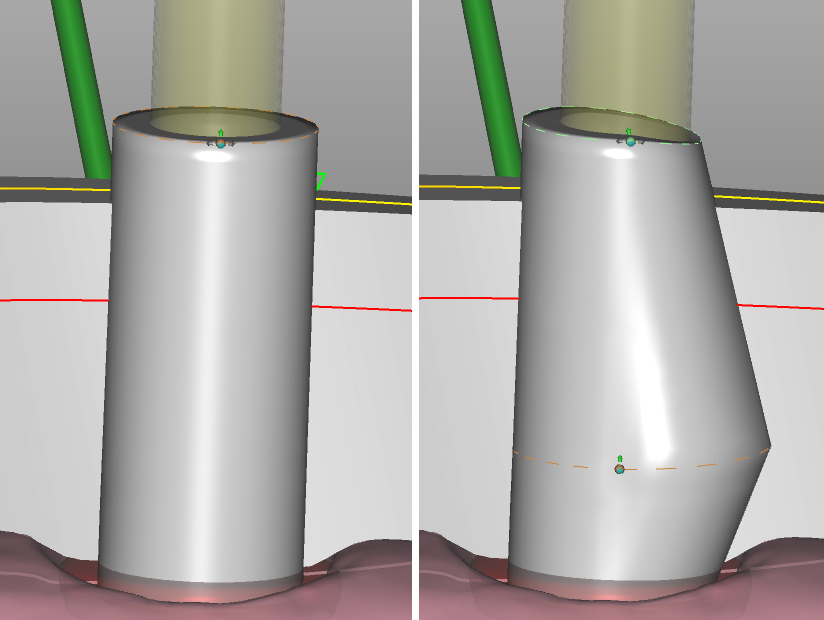
By default, pillars will have a cylindrical shape and follow the axis of the implant. You can change this by setting a margin on the pillar that separates the pillar into two parts: one part follows the implant axis, the other part follows the insertion axis (meaning that it is blocked out).
To add this control line:
| Hold <Ctrl+Shift> and click on the pillar at the height where you want to position the orange separation line. |
The image below illustrates how this affects the shape of the pillar.
Left: Cylindrical shape (default).
Right: Orange control line inserted by <Ctrl+Shift+Click> - the part above the orange line is now blocked out following the insertion axis (shown in green in the image).
| The 'Min. pillar angle' which you can set in the "Advanced" tab will only be applied above the orange line. |
Extending the bar profile library
| We strongly recommend that you use only the supplied bar library. Although it is possible to extend the bar library yourself, as described below, using inappropriate shapes or meshes may result in problems. In other words, there's no guarantee it will work - so please do not bother technical support regarding problems related to the unofficial extension of the bar library. The following instructions are targeted at operators that are experienced with industrial CAD software, such as SolidWorks |
In addition to the XML-based parametric shape definitions in the shipped .barProfile files under DentalCADApp\library\bar, the bar profile library may also be extended using STL files, if the meshes meet certain characteristics.
The orientation of the mesh must be as follows:
- Occlusal direction: Y
- Direction of the bar: Z
- Lingual direction: X
- Recommended triangle edge length: 10µm
Proceed as follows:
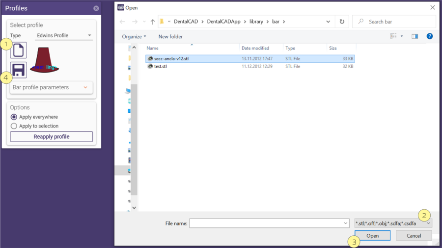
- Click the "Open Directory" icon [1].
- Select "*.stl;*.off;*.obj;*.sdfa;*.csfda" in the file type selection drop-down [2], then click Open [3].
- In the message box that pops up, chose if you wish to have the profile fixed or user-changeable.
- Inspect the resulting bar. If results are not satisfactory, work on the STL (e.g. use different export settings in the software that generated it, change orientation, etc) and try again.
- To save the profile in .barProfile format, click the "Save" icon [4].
| If you save the .barProfile file under DentalCADApp\library\bar, then it will automatically show up in the 'Select profile' list the next time you use the bar module! |
Designing superstructures over bars
Once your bar is finished and produced, you can design a superstructure:
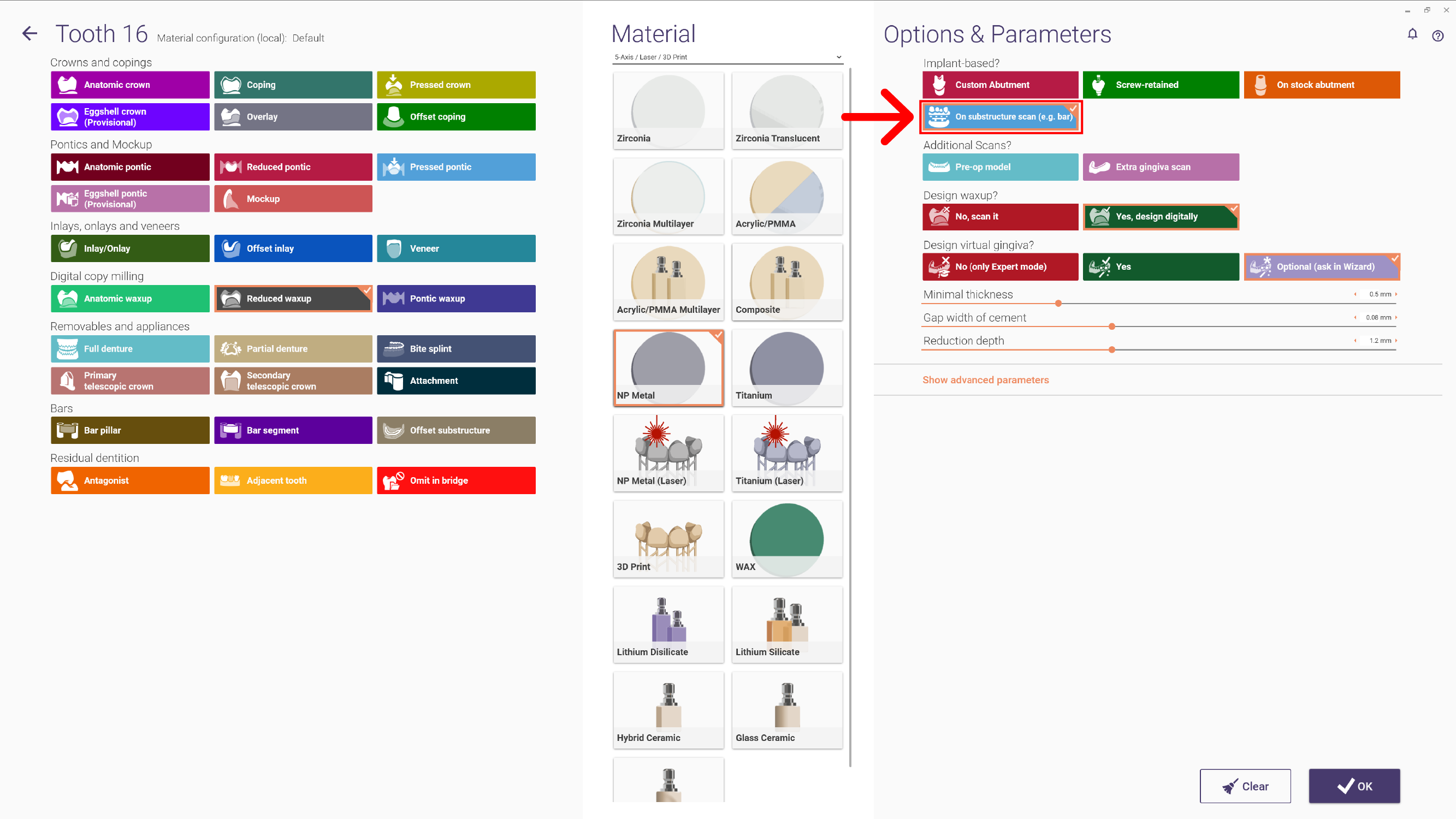
- Set up a new case with the indications that go on top of the bar, and select "Substructure (e.g. bar)" under "Implant based?" in DentalDB, as shown in the image below.
Note: If you do not see that option, contact your reseller or the provider of your material configuration file. The option is available since 2016 Version of exocad DentalCAD.
- Scan the finished bar, and proceed to "Design" again. Follow wizard instructions for the superstructure design.
Why re-scan model with bar, as a new case?
Some customers would prefer to design everything digitally in one go. We do not recommend this at this point. For various reasons, the milled result of a complex shape will always be slightly different than the original design - depending on milling strategy, tools, manual post-processing such as polishing/removing supports, etc. Some milling centers may manage a "full digital" process for selected bar shapes, but generally, re-scanning is the safer path to good results. In the case of simple shapes such as abutments, the software can predict quite well how the final result will look - which is why the exocad Implant Module supports designing everything in one go for abutments. For complex bars, it's a different situation.
