Abutment design


Contents
Control points

There are control points [1] on the abutment which can be moved inwards, outwards, up, and down to change the abutment's shape. Note that the software ensures that undercuts are avoided, and production-specific design restrictions are enforced. Therefore, there is - intentionally - some restriction in the movement, and moving one control point can cause another control point above or below to move as well.
Fissure line [2] is activated by default enabling the adjustment of the depth of the central fossa. The outer control points are connected to the central control point via the dashed line and can be moved together. The joint movement is guided by the middle control point. This allows the height of the fissure to be determined in a coordinated manner. For anterior teeth, this controls the incisal edge.
With the green control point [3] between the arrows in the center of the abutment, you can adjust the overall abutment height.
The green round 3D widget [4] above the abutment allows to flatten the abutment top. To undo the action, click the Undo button.
|
Wizard tab: Top

In the Abutment Style section, the software initially suggests an abutment style based on the tooth number and the currently defined design parameters.
Four abutment styles are available:
- Cylindrical [A] – Features a small shoulder width and reduced angularity, with smooth, rounded edges.
- Angular [B] – Provides a moderate shoulder width and pronounced angularity.
- Standard [C] – Offers average shoulder dimensions and moderate angularity.
- Legacy [D] (3.2 software) – Replicates the behavior of version 3.2, without advanced shape customization.
To select a different style, click the arrow icon [1] to expand the menu and choose the desired abutment design.


[3] Select to maintain a constant shoulder size


Click Apply angle everywhere [6] to apply the adjusted minimum angle parameter.
To apply certain controls, activate the options:
[7] Connect fissure controls checkbox is active, the outer control points are connected to the central control point via the dashed line and can be moved together. The joint movement is guided by the middle control point. This allows the height of the fissure to be determined in a coordinated manner. For anterior teeth, this controls the incisal edge.
[8] Keep design within anatomy checkbox ensures the abutment is not higher than the anatomic shape, not intersecting with the previously placed model tooth.
 Use adjust insertion direction [9] to open the insertion direction processor during the abutment design mode. Specially useful to guarantee unique insertion direction for bridges.

Additionally, use the three dots [10] to expand the following options:
Restore initial shape [A] but use the parameters you set in the dialog.
Reset customized parameters [B] will reset all parameters to the original values of the abutment design.
Save custom design [C] gives the opportunity to save the current values as a new custom abutment design as shown below.
 Click to open custom designs folder [D] .
| Scene files created with the previous abutment design can still be loaded and used with the special style "Legacy". Switching between old and new styles requires a complete reset of the design. |

Distance to occlusal surface
It is also possible to tell the software to enforce a certain space between the anatomy and the abutment with the Spacing slider [11]. If Auto Adapt checkbox [12] is set, both the distance and the occlusal shape of the abutment are precisely offset from the chewing surface.
If a change to [11] or [12] is entered, these changes will only be applied if either the Apply [13]. The Apply button will both reduce and grow the shape in order to reach the desired distance values.
 With activating the checkbox Distance to anatomy (on abutment) [14], you can visualize the distance of the anatomy to the abutment, the visualization is displayed on the abutment. The visualization is color-coded from red (low distance), to blue (high distance).
 You can also have a measurement Distance to abutment [15] displayed on the anatomy.
Wizard tab: Bottom
Use this tab to correct your abutment bottom design, without going backward in the wizard. For details, see section "Generate abutment bottoms"
Wizard tab: Advanced
| In the ADVANCED tab, you can adjust the abutment design and emergence profile at the same time. |

Use this tab to adjust the profile borders, angulate screw channels, set the milling parameters, and adjust the margins.
The slider Height [1] sets the minimum height of the abutment profile border.
The slider Radius [2] controls the round-off at the sharp edge of the border.
[5]: Allows you to move all points that define the border (abutment margin) at the same time, inwards, outwards, up or down.
[6]: These controls allow you to stick or unstick all of the border control points to the gingiva (tissue).
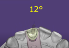
Angulated screw channels

Angulated screw channels [3] is possible, if the configuration of your exocad software, and the implant library used, allows this.
There are two possibilities to do it:
- Clickable

Click anatomic surface, pre-op or waxup scan to let the screw channel go through this point.
Hint: Hold CTRL and click to reset the previously manually defined angle.
- Draggable

Define screw channel angle by dragging an arrow.
Holding CTRL and SHIFT restricts angle movement to the current angulation plane.
Holding CTRL and 'X' restricts angle movement to the implant analog plane.
Holding CTRL and 'I' snaps the angle to the nearest Integer value.
Holding CTRL, SHIFT and 'I' snaps the angle to intervals of 1°.
See our video tutorial for details.

Expanding the Milling Parameters [5] control reveals the following:
- [8] Min thickness sets the minimum thickness of the abutment's axial walls.
- [9] Diam. can be used to set the diameter of the tool used to mill the abutment, also known as the tool compensation. You should add at least 0.2mm to the smallest tool size.
- [10] Tool sets the diameter of the tool used to mill the suprastructure (crown or coping).
- [11] Screw Distance keeps a minimum distance of the abutment to the screw channel. The control points can't be set closer to the screw channel than this value.
- [12] Margin is the minimum angle of the margin of the abutment.
| You even get the best fitting between abutment and suprastructure if you mill both parts at the same time. This is why we fully consider parameters [9] and [10] during the design. If these parameters are set to zero, you will get more freedom in design, but you have the problem that the sharp edges at the top of the abutment cannot be milled because of the tool diameter. You need to adjust these values to match your milling system. |
Q&A
What’s the difference between a custom abutment and a stock abutment?
A custom abutment is designed in DentalCAD based on the patient's scan, precisely matching the implant angle and gingival contours for an optimal emergence profile and easier hygiene; a stock abutment (prefabricated) has a standardized shape and size, selected chair-side without customization.
How do I keep two or more custom abutments parallel for a bridge?
When designing multiple abutments, set a unified insertion axis by selecting the option Unified insertion direction for bridges. This ensures parallel alignment of abutments. For further guidance, refer to this section.
How do I enable angulated screw channels?
To enable angulated screw channels, go to the Advanced tab and select the Angulated screw channel section. This feature must be supported by your implant library. You can adjust angles either by clicking directly on the anatomy or by dragging the arrow with specific keyboard shortcuts for precise control. Visit this section for further information.