Abutment Bottoms


Contents
Bottoms
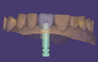
To design the bottom of the abutment, the part below the gingiva, you might follow these steps. The gingiva is displayed transparent, so that you can look through it for better design control.
| To define the opacity, right-click the part you want to change and choose 'Visual properties' in the context menu. Then choose the opacity value. |


Any change done using these controls applies to all abutment of the whole restoration. If you want to change only one abutment, don't use the sliders. Use the free-forming mode instead by clicking the checkbox Free-form bottom [3]. Left-click where you want to add material, and the material will be added there. Click [4] to open the dropdown menu and access the distance to gingiva options.
| While holding the <SHIFT> key and left-clicking, you can remove material. Left-clicking adds material only locally. If you want to add material all around, you can hold the <CTRL> key while clicking left. |

You can also visualize intersections with the gingiva by activating the checkbox Visualize [4] so you can see how much pressure is applied on the gingiva or how far the distance from the gingiva is.
- Blue color indicates that there is space for the gingiva.
- Red color indicates that there is pressure on the gingiva.
You can control the scale of the visualization by moving the sliders. This is important because we need a very precise control for the pressure we want to apply on the gingiva. The upper checkbox is for distance control [5], and the checkbox below is for intersection control [6]. The distance and intersection are controlled for all abutments by the values in the fields left from the limit checkboxes. If the values are set to zero, the emergence profile is adapted to the gingiva scan.

The toggle disk - meaning of the color
You can drag these points [1] by dragging the arrows or the point itself. When using the arrows, the movement is restricted to the arrow direction. The point can be dragged freely in all directions.
If you want to create a very complex shape, it is useful to add more control points.
Rose-colored means that the point is attached to the gingiva.
Below each control point, there is a toggle disk [2]. Using this disk, you can change the color of the control point to green.
In the green mode [3] the control point is detached from the gingiva, and you can move it freely away from the gingiva. You can set pressure on the gingiva by intersection.
| To add a control point, click the margin of the emergence profile while holding <CTRL>.
To remove a control point, click it, hold the left mouse button, and right-click. |
| Holding <CTRL> while clicking the toggle disc [2] you can switch all control points simultaneously between green (unstick to gingiva) or pink (stick to gingiva). |
| Click on the pencil as shown below to access the hotkeys list. |

Advanced


With Angulated screw channels [3] the angulation of screw channels is possible, if the configuration of your exocad software, and the implant library used, allows this. Choose Clickable [A] and click a mesh object in the scene to angulate the screw channel. Select Draggable [B] and use the appearing sphere and arrow handles to reposition the screw channel.
Click Reset all [C] to reset the screw channel. This feature is available only if the implant library allows for angulated screw
channels. By default, the angulation is limited by 20° if not otherwise defined in the implant library.
The entire margin can be moved together with the Move All Margins [4] controls.
With Unstick all [5], you can detach all control points of all constructions. All control points and toggle disks switch to green. Expand the dropdown menu to Force to predefined radius [D] which will detach all control points from the gingiva scan and force to predefined radius. Force to predefined height [E] to detach all control points from the gingiva scan and force to predefined height. The opposite can be reached by clicking Restick all [6], so that all control points and toggle disks switch to pink color.
Q&A
How can I quickly adapt the abutment bottom to the trimmed gingiva to achieve a perfectly fitted, uniformly compressed emergence profile?
After finishing the standard abutment bottoms step, switch to Expert Mode, right click the abutment you wish to adjust and choose Free Form Emergence Profiles. Use the Free-Form tools to fine tune the shape, then under Adapt select the Emergence Profile button.

How do I edit only one abutment bottom without changing the others?
To adjust a single abutment without affecting the others, use the Free-form bottom tool under the Shape section instead of the global sliders, this allows localized control over the emergence profile. Alternatively, switch to Expert Mode, right-click the specific tooth you want to modify, and select the Abutment Bottoms option from the context menu. This reopens the tool for that individual abutment, enabling precise, independent adjustments.