Generating connectors


Connectors will be generated wherever it has been previously defined in the DentalDB.

You can customize connectors in various ways. The minimum size of the connector may be defined either by its cross-sectional area, or by its height/width.
- Toggle between the two modes using the radio buttons [1], and perform your adjustments using the slider [2].
- To Visualize the connector thickness, click [3]. You can also switch between different predefined shapes by clicking Shapes [4].
- The Minimum basal distance [5] allows adjusting the minimum distance of the connector shape from jaw scan data, or from the designed bottom of a virtual gingiva case.

- Use the Advanced placement [6] to adjust the position of the connector in relation to the library tooth:
- Adjusting Below approx. contact, the higher the value set using the slider, the lower the connector is placed below the defined/estimated approximal contact point of the library tooth.
- Adjusting Behind approx. contact (lingual), the higher the value set using the slider, the further behind on the lingual side the connector is placed below the defined/estimated approximal contact point of the library tooth.
- Adjusting Below approx. contact, the higher the value set using the slider, the lower the connector is placed below the defined/estimated approximal contact point of the library tooth.
- Check the box Apply any changes automatically and the connector position changes automatically on user input changes. Note that a fast computer is required for that feature, especially when dragging the sliders by mouse.
- Click Apply placement now, it resets the connector placement using the newly defined parameters.
- To apply your changes, click Apply cross section/Shape change [7].
- Multi-view design [8] allows to edit individual connectors and their curves using multiple 2D/3D views at the same time. If enabled, all changes are only applied to the selected connector. The selected connector can be changed using the arrow button or by clicking/editing a specific connector in the main 3D view.
| Dragging the connector will change its position on both sides – to change the docking place of the connector only on one side, hold <CTRL> and click the tooth to change the position of the docking point [9]. |
| Any changes you make will be applied to all connectors. To apply different parameters/shapes to specific connectors in the construction, close the wizard and use the context menu (right-click the connector, choose 'Connectors...'. Alternatively, you can customize the connectors using the 'Free' tab, as explained below.) |

- To change the connector position [9], simply drag and drop the connector using the mouse. It will readapt itself to the teeth once you drop it at its new position.
- Moving the mouse over the connector shows the measurements of the connector [10].
- The multi-view has advanced options available, clicking on the upper right side [11], allows to reset the view, move into the next or previous connector, copy the ring to another position, and copy connector to or from another position.
- Click on the central points of the connector to drag the ring and change the position [12].
- The multi-view advanced options are also available by clicking with the right mouse button on the window [13].
- It is also displayed an additional line [14] in the Mult-view of the Antagonist scan helping to avoid intersections of the connectors. If available, you can additionally see wax-up bottoms, jaw scan, antagonist, reconstructed teeth, and virtual gingiva.

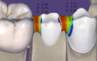
| When generating connectors, the software tries to enforce the minimum cross-sectional area, or the minimum height/width. In some rare cases, this may fail due to space restrictions. The connector will then be displayed in red. This situation needs manual work to be resolved – try changing the location of the connector (by dragging & dropping it, or by repositioning the docking points), or use the connector free-forming as described below. |
Free tab
Switch to the "Free" tab to further customize your connectors, or to visualize connector thickness.
 You can edit connectors by moving control points. When you move the mouse close to one of the control points, it will grow and spawn arrows.
- Drag and drop the control point itself for free movement in all directions
- Drag and drop one of the arrows for a movement that is restricted to the direction of the arrow
The multi-view design option is also available, enabling multiple 2D/3D views at the same time. All changes are only applied to the selected connector.
| To insert additional control points, hold <CTRL> and click on the green line in the center of the connector, at the location where you'd like to insert the new control points. The more control points you add, the more freedom in designing complex connectors you have. To move several control points at once, hold <SHIFT> while dragging one of the green control points. |
| With great power comes great responsibility – since you are free to shape the connectors as you desire, you can also make the connectors thinner than specified by the material parameters. If you design the connector substantially thinner as specified, the software will mark the approximate area which is too thin in magenta. Whenever you see a partially magenta-colored connector, do change its shape to make it thicker – unless you are willingly taking the risk of designing construction that may not be stable enough. |