모델 분석 개념
올바른 모델 분석은 모든 설정의 필수이기 때문에 최대한의 지식과 신념을 가지고 세심한 주의를 기울여 완료해야 합니다. 모델 분석은 대부분 작업자가 CAD에서 완료하며, 상악과 하악의 해부학적 특성을 설정하고 이를 방향과 평면으로 자동 일치시키는 작업이 포함되며, 이는 치아의 디지털 설정의 기초로 사용됩니다
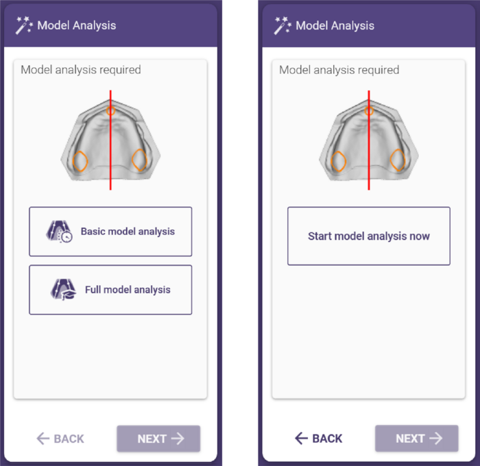
모델 분석 마법사 모드
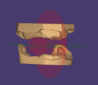
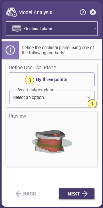
모델 분석의 개별 단계는 화면 왼쪽에 있는 마법사 창에 요약되어 있으며, 두 가지 중요한 구성 요소로 이루어져 있습니다. 모델 분석의 모든 단계는 창 상단 [1]에 리스트로 나열됩니다. 필요한 모델 분석 단계의 아이콘을 마우스 왼쪽 버튼으로 클릭하면 이전 단계로 돌아갈 수 있습니다. 창의 두 번째 영역 [2]에서는 현재 모델 분석 단계에 대한 설명과 미리 보기를 제공합니다.
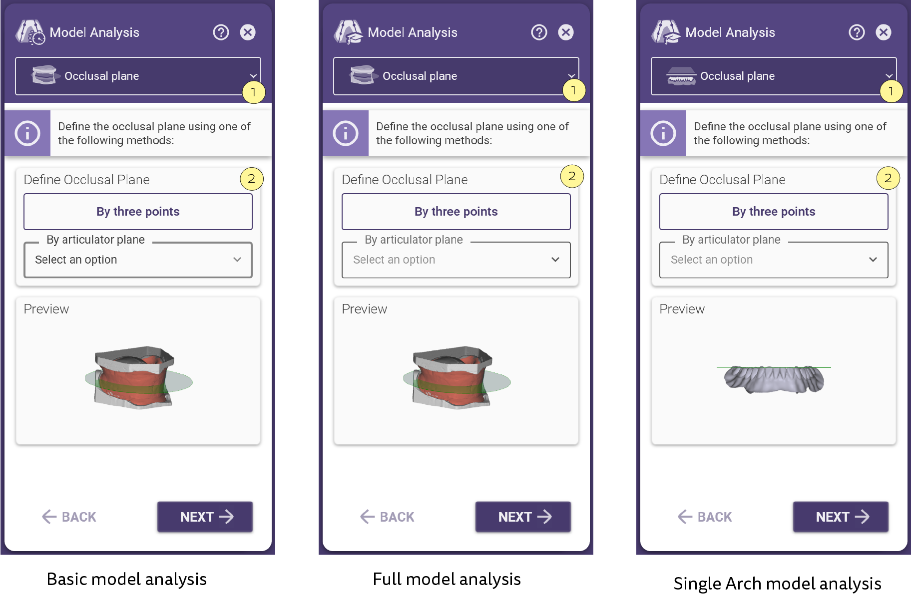
 | 편악 덴쳐의 경우 바이트 림 스캔이 필요하지 않지만, 대합치에 대한 모델 분석이 수행이 필요합니다. |
|
교합 평면 정의
교합면은 치아를 설정하는 동안 수직 방향으로 사용됩니다.
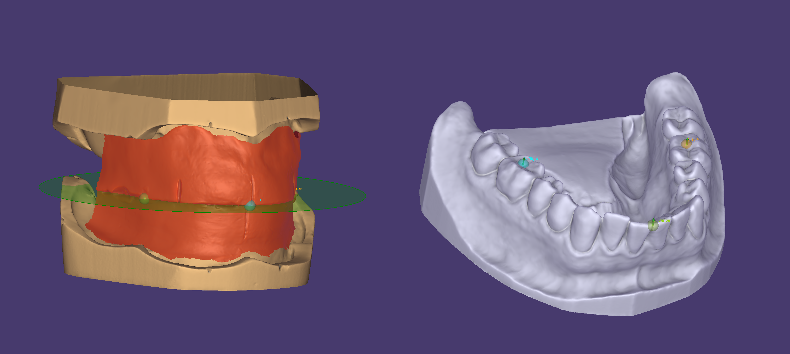
이는 정상교합 치열의 세 점을 사용하여 정의됩니다:
- 하악 제1대구치의 원심 협측 교두정
- 하악 중절치 중앙 지점
교합면을 정의하는 방법에는 3점 방법 [3]과 교합기로부터 정의하는 방법 [4]의 두 가지 방법이 있습니다.
|
|
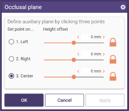
'3점을 지정하여 교합 평면 만들기' 기능을 사용하면 진단 모델 또는 심미적 템플릿을 사용하여 교합면을 정의할 수 있습니다.
• 교합면을 정의하려면 위에서 설명한 위치에서 세 점을 클릭한 다음 '적용' 버튼을 클릭합니다.
• 이후에 포인트(교합면)를 조정하려면 마우스 왼쪽 버튼을 누른 상태에서 포인트를 드래그합니다.
• 다른 방법으로는, 무치악에 세 개의 점을 추가하고 슬라이드를 사용하여 점과 교합면의 거리를 설정합니다.
•개별 거리를 지정하려면
각 지점에서 슬라이드 컨트롤 오른쪽에 있는 자물쇠 아이콘을 클릭합니다.
|
|
• 교합기 평면 정의 [4]
사용 가능한 심미적 템플릿이나 진단 모델이 없는 경우, 미리 정의된 교합면을 사용할 수 있습니다. 드롭다운 메뉴 중 하나를 선택하면 교합면을 자동으로 생성하고 시각화 할 수 있습니다.
기본 모델 분석
|
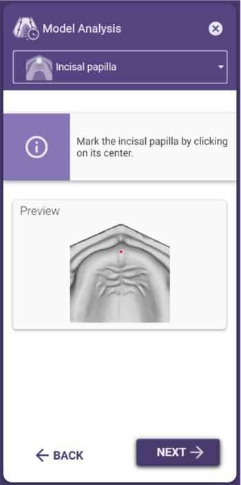
상악의 절치 유두 설정
• 절치 유두의 중앙에 점을 클릭하여 절치 유두를 정의합니다.
• 필요한 경우 포인트를 왼쪽 클릭하고 드래그하여 이동합니다.
|
|
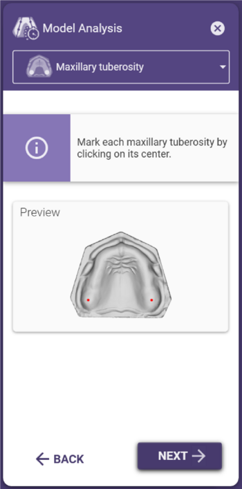
상악 결절 설정
• 상악 결절의 중앙에 점을 표시하여 각 상악 결절을 정의합니다.
• 필요한 경우 포인트를 왼쪽 클릭하고 드래그하여 이동합니다.
|
|
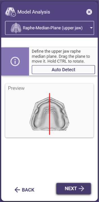
상악의 봉합(정중)면 설정
상악 정중선은 이전에 정의된 절치 유두 및 상악 결절을 기반으로 자동으로 생성됩니다.
중앙 평면을 수동으로 조정하려면:
• 중앙선을 클릭하고 드래그하여 이동합니다.
• 중앙선을 중심으로 회전하려면 Ctrl 키를 누른 상태에서 드래그합니다.
• 회전 지점을 클릭하고 드래그하여 위치를 이동합니다.
|
|
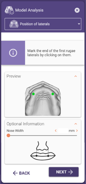
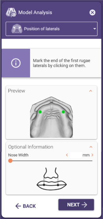
상악 견치 위치 설정
첫 번째 구개주름의 끝은 견치의 대략적인 위치를 나타냅니다.
• 각 팁을 한 번씩 클릭하여 포인트를 만듭니다.
• 환자의 비강 폭을 이용하여 전치 너비를 선택한 경우 부가 정보 창을 열어 측정된 폭을 입력합니다. 이후 단계에서 추천되는 덴쳐 라이브러리는 여기에 입력한 값을 기준으로 표시됩니다.
• 필요한 경우 포인트를 왼쪽 클릭하고 드래그하여 이동합니다.
이 위치는 덴쳐 전치 라이브러리의 위치를 계산하고 초기 방향 설정으로 사용됩니다.
|
|
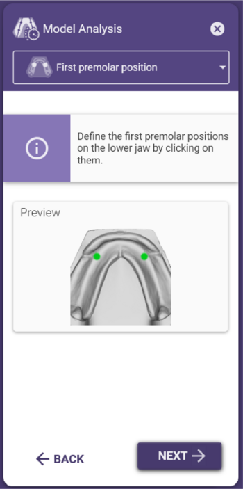
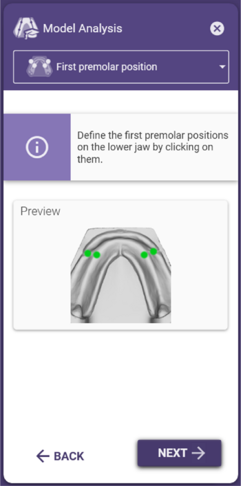
하악 제1소구치의 위치 설정
• 왼쪽 클릭으로 하악 소구치의 위치를 소구치의 연장선 또는 치조골 융기 중앙에서 약간 더 원심쪽으로 표시합니다.
• 필요한 경우 포인트를 왼쪽 클릭하고 드래그하여 이동합니다.
하악 제1대구치의 위치는 구치부 크기를 선택하는 기준의 일부이며 하악의 바깥/안쪽 통계치 생성에 사용됩니다.
|
|
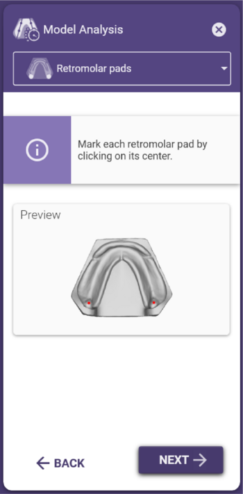
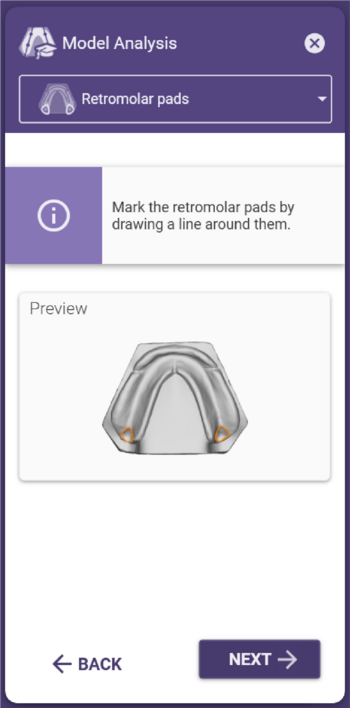
하악 후구치 삼각 설정
• 각 후구치 삼각의 중앙을 왼쪽 클릭하여 표시합니다.
• 필요한 경우 포인트를 왼쪽 클릭하고 드래그하여 이동합니다.
후구치 삼각을 표시하는 것은 하악, 바깥쪽 및 안쪽 하악 정렬을 정의하는 기초가 됩니다.
|
|
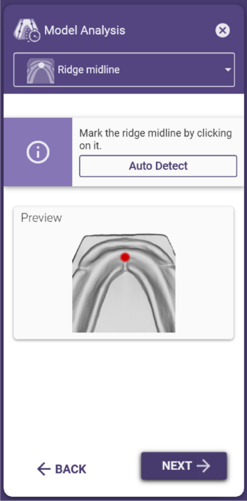
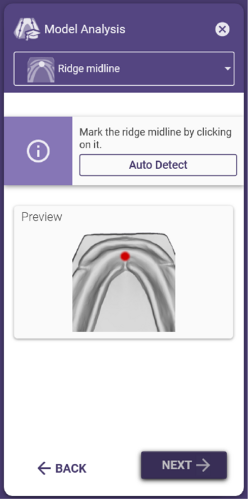
하악의 전치부 융선의 중앙 설정
• 이 포인트는 자동으로 생성됩니다.
• 필요한 경우 하악의 중앙선을 따라 점을 클릭하고 드래그합니다.
해당 설정은 전치의 기저면을 배치할 때 기준점으로 사용됩니다.
|
|
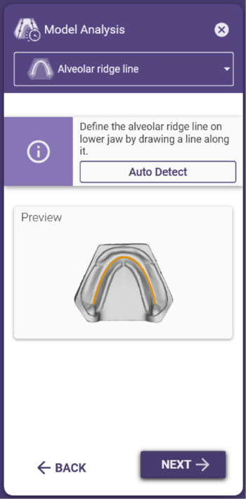
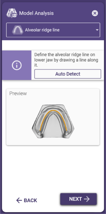
하악의 치조 융선 중앙 설정
• 하악의 치조골 중앙선이 자동으로 생성됩니다.
• 후구치 삼각의 근심은 치조골 융선에서 가장 먼 지점으로 사용됩니다.
• 자동 감지는 보조 수단일 뿐이며 필요한 경우 직접 확인하고 조정해야 합니다. 이렇게 하여야 다음 단계에서 제1대구치 위치를 문제없이 감지할 수 있습니다.
• 치조골 라인을 변경하려면 초록색 포인트를 클릭하고 원하는 대로 드래그합니다.
• 마우스 왼쪽 버튼을 누른 상태에서 마우스 오른쪽 버튼을 동시에 눌러 포인트를 삭제합니다.
• 왼쪽 클릭하여 선에 점을 추가합니다.
치조골 융선은 초기 전치부 셋업의 방향으로 사용됩니다. 또한 치조골 융선의 가장 깊은 영역이 결정되어 제1대구치의 위치로 설정됩니다. 표시된 치조융선의 원심점은 정지선의 한계로 사용되므로(하악의 정지선 설정 참조), 후구치 삼각 위로 연장해서는 안 됩니다.
|
|
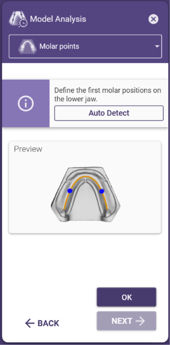
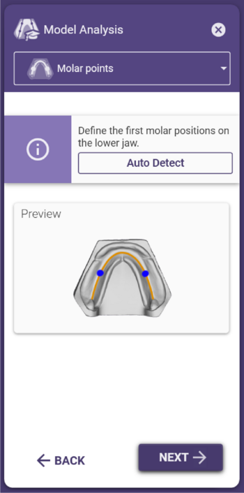
하악 제1대구치 설정
• 제1대구치의 위치는 자동으로 생성되는 포인트들을 사용하여 하악에서 정의됩니다.
• 교합면을 기준으로 치조골 융선의 가장 깊은 지점에 위치해야 합니다.
• 구치부 깊숙이 심한 발치 상처가 있는 경우, 이 부위가 제1대구치의 위치로 잘못 결정될 수 있습니다.
• 필요한 경우 포인트를 드래그하여 이동합니다.
하악 제1대구치의 위치는 올바른 크기의 구치부 치아를 선택하는 기준입니다. 제1대구치는 저작의 중심이기 때문에 교합면을 기준으로 치조골 융선의 가장 깊은 부위에 위치해야 합니다.
|
전체 모델 분석
|
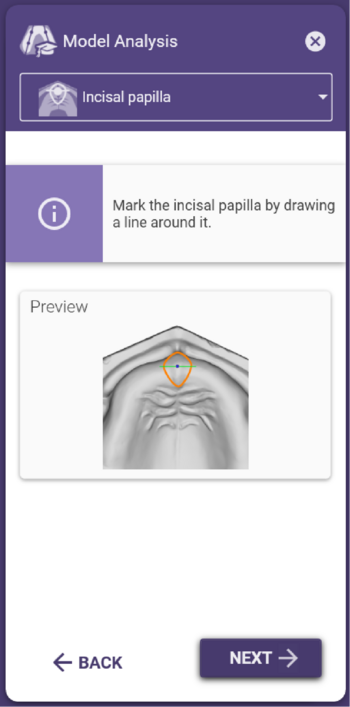
상악의 절치 유두 설정
• 바깥쪽 가장자리에 있는 점을 클릭하여 절치 유두를 그려 정의합니다.
• 필요한 경우 포인트를 왼쪽 클릭하고 드래그하여 이동합니다.
• 마우스로 포인트를 가리킨 상태에서 Delete 키를 눌러 포인트를 삭제합니다.
|
|
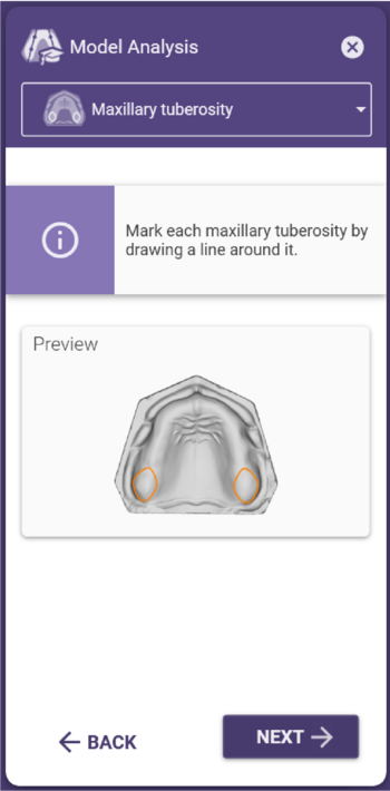
상악 결절 설정
• 상악 결절의 바깥쪽 가장자리에 있는 점을 클릭하여 그려서 상악 결절을 정의합니다.
• 필요한 경우 포인트를 드래그하여 이동합니다.
• 마우스로 포인트를 가리킨 상태에서 Delete 키를 눌러 포인트를 삭제합니다.
|
|
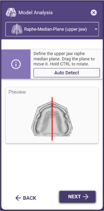
상악의 봉합(정중)면 설정
• 상악 중앙선은 이전에 정의된 절치 유두 및 상악 결절을 기반으로 자동으로 생성됩니다.
• 중앙 평면을 수동으로 조정하려면 중앙선을 클릭하고 필요에 따라 드래그합니다.
• 중앙선을 중심으로 회전하려면 Ctrl 키를 누른 상태에서 드래그합니다.
• 회전 지점을 클릭하고 드래그하여 위치를 이동합니다.
|
|
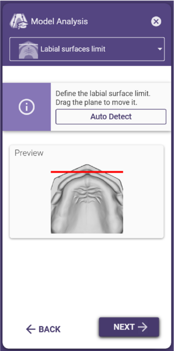
상악의 순측 전정 라인 설정
• 순측 전정 라인은 절치 유두 앞 8mm 전방에 자동으로 생성됩니다.
• 라인을 수동으로 조정하려면 필요에 따라 드래그합니다.
|
|
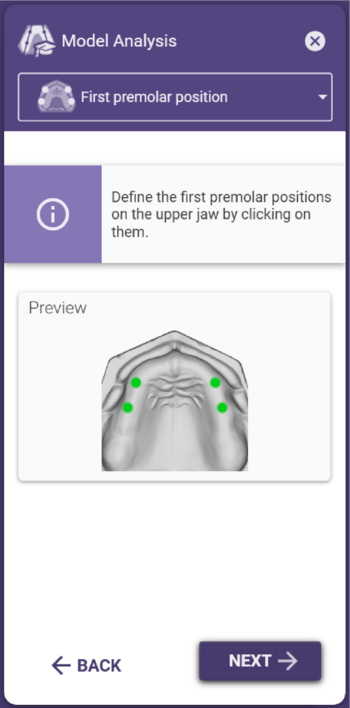
상악 제1소구치의 위치 설정
• 첫 번째 큰 구개골의 끝은 견치의 대략적인 위치를 나타냅니다. 각 끝을 한 번씩 클릭하여 표시합니다.
• 환자의 비강 폭을 사용하여 올바른 전치부 크기를 선택할 경우, 마법사 창에 측정된 폭을 입력합니다. 나중에 추천되는 덴쳐 치아 라이브러리는 여기에 입력한 값을 기준으로 합니다.
• 필요한 경우 포인트를 왼쪽 클릭하고 드래그하여 이동합니다.
이 위치 결정은 덴쳐 전치부 라이브러리의 위치를 계산하고 초기 전치부 세트의 방향 설정으로 사용됩니다.
|
|
상악 제1대구치의 위치 설정
• 이전에 정의한 견치 위치 뒤에 있는 소구치 너비를 클릭하여 상악 소구치의 위치를 정의합니다.
• 필요한 경우 포인트를 왼쪽 클릭하고 드래그하여 이동합니다.
|
|
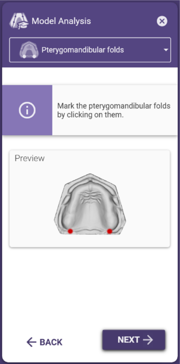
상악의 익상편 주름의 결정
• 익상편을 클릭하여 위치를 정의합니다.
• 필요한 경우 포인트를 왼쪽 클릭하고 드래그하여 이동합니다.
|
|
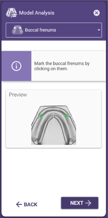
하악의 누공 설정
• 왼쪽 및 오른쪽 소대 클릭 포인트의 위치를 정의합니다.
• 필요한 경우 포인트를 드래그하여 이동합니다.
하악의 소대가 완전히 보이지 않는 경우가 많으므로 이런 경우 예상 위치에 포인트를 배치합니다.
|
|
하악 제1소구치의 위치 설정
• 하악 소구치의 위치를 정의하려면 클릭하여 소대의 연장선 또는 치조골 융선 중앙에서 약간 더 원심쪽으로 표시합니다.
• 필요한 경우 포인트를 드래그하여 이동합니다.
하악 제1대구치의 위치는 구치부의 올바른 크기를 선택하기 위한 기초가 되며, 하악의 기본 통계치, 하악의 외측 및 내측 조절에 사용됩니다.
|
|
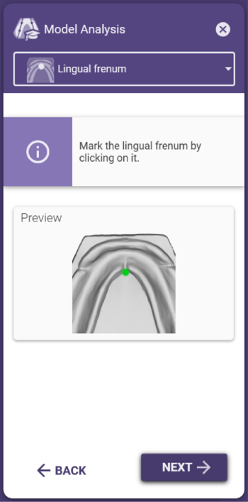
하악의 설소대 설정
• 설소대를 정의하려면 클릭합니다.
• 필요한 경우 포인트를 드래그하여 이동합니다.
|
|
하악 후구치 삼각 설정
• 경계를 점으로 클릭하여 구후 삼각을 정의합니다.
• 필요한 경우 포인트를 드래그하여 이동합니다.
• 마우스로 포인트를 가리킨 상태에서 Delete 키를 눌러 포인트를 삭제합니다.
• 표시된 구후 삼각은 하악, 바깥쪽 및 안쪽의 조절을 통한 배열의 기초가 됩니다.
|
|
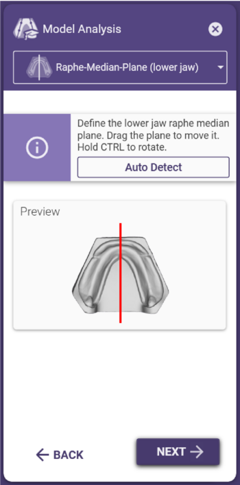
하악의 정중선 설정
• 하악의 정중선은 자동으로 결정됩니다.
• 정중선을 수정하려면 필요에 따라 중앙을 클릭하여 드래그합니다.
• 회전 지점을 중심으로 회전하려면 Ctrl 키를 누른 상태에서 드래그합니다.
• 회전 지점을 클릭하고 드래그하여 위치를 이동합니다.
|
|
|
하악의 치조선 중앙 설정
• 이 포인트는 자동으로 생성됩니다.
• 필요에 따라 하악의 정중선을 따라 점을 드래그합니다.
치조선 중앙의 표시는 전치의 기저면을 배치할 때 기준점으로 사용됩니다.
|
|
하악의 순측 전정선 설정
• 순측 전정선은 자동으로 계산되며 순측 점막의 가장 깊은 지점을 통과합니다.
• 라인을 수동으로 조정하려면 원하는 대로 라인을 클릭하고 드래그합니다.
|
|
하악의 치조선 설정
• 하악의 치조 융선이 자동으로 생성됩니다.
• 후구치 삼각의 근심 위치는 치조 융선의 가장 먼 지점으로 사용됩니다. 자동 감지는 보조적인 기능일 뿐이므로 직접 확인하고 필요한 경우 수정해야 합니다. 이것이 다음 단계에서 제1대구치의 위치를 문제없이 감지할 수 있는 유일한 방법입니다.
• 치조 융선을 수정하려면 녹색 포인트를 클릭하고 원하는 대로 드래그합니다.
• 마우스 왼쪽 버튼을 누른 상태에서 마우스 오른쪽 버튼을 동시에 눌러 포인트를 삭제합니다.
• 왼쪽 클릭하여 선에 포인트를 추가합니다.
치조융선은 초기 전치부 셋업의 방향으로 사용됩니다. 또한 이 선에서 치조골 융기의 가장 깊은 영역이 결정되어 제1대구치의 위치로 지정됩니다. 표시된 치조 융선의 원심 끝점은 정지선의 한계로 사용되므로(하악의 정지선 설정 참조), 구후 삼각 위로 연장해서는 안 됩니다.
|
|
하악 제1대구치 설정
• 하악 제1대구치의 위치는 자동으로 생성되는 포인트로 정의됩니다.
• 교합면을 기준으로 치조골 융기의 가장 깊은 지점에 위치해야 합니다. 구치부의 깊은 심한 발치 흔적의 경우, 제1대구치의 위치가 잘못 결정될 수 있습니다.
• 필요한 경우 포인트를 왼쪽 클릭하고 드래그하여 이동합니다.
하악 제1대구치의 위치는 올바른 크기의 구치부 치아를 선택하는 기준의 일부입니다. 제1대구치는 저작의 중심이 이 부위에 있기 때문에 교합면을 기준으로 치조골 융기의 가장 깊은 부위에 위치해야 합니다.
|
|
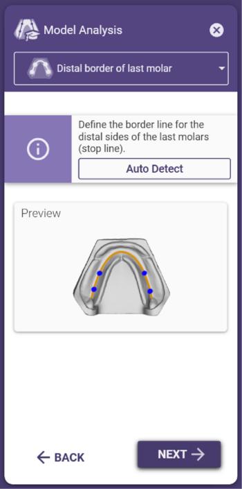
하악의 정지선 설정
• 정지선은 교합면을 기준으로 치조 융선의 가장 깊은 지점에서 연장되는 22.5° 각도로 자동으로 생성되며 소프트웨어에서 치조골 융기 윤곽의 점들로 표시됩니다.
• 치조 융선이 끝나기 전에 이 각도를 초과하지 않으면 정지선은 표시된 치조선의 가장 먼 지점에 해당합니다.
• 필요한 경우 포인트를 왼쪽 클릭하고 드래그하여 이동합니다.
정지선은 식립 부위의 원심 경계를 나타내므로 제2 대구치를 식립할지 여부를 결정합니다. 해부학적 이유(예: 평평한 턱)로 인해 22.5°의 각도를 얻을 수 없는 경우, 치아는 후구치 삼각의 근심측 경계를 넘어 확장되지 않아야 합니다.
|
|
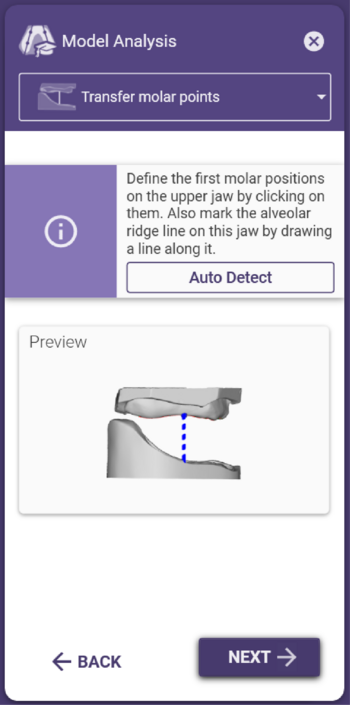
치조선 및 상악 제1대구치 설정
• 상악에 치조 융선이 자동으로 생성됩니다. 하악 제1대구치의 위치가 상악의 치조선으로 옮겨집니다.
• 치조선을 변경하거나 조정하려면 녹색 포인트를 클릭하고 원하는 대로 드래그합니다.
• 마우스 왼쪽 버튼을 누른 상태에서 마우스 오른쪽 버튼을 동시에 눌러 포인트를 삭제합니다.
• 왼쪽 클릭하여 선에 포인트를 추가합니다.
• 일반적으로 자동으로 감지된 치조선을 조정해야 하므로 제1 대구치의 협측 또는 순측 위치도 조정해야 합니다.
치조선은 하악 제1대구치 위치를 상악으로 옮기는 데 사용됩니다. 상악 제1대구치 위치는 바깥쪽 영역의 기준점입니다.
|
|
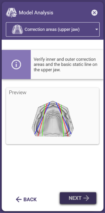
상악 수정 영역
내부 및 외부 영역을 확인합니다.
|
|
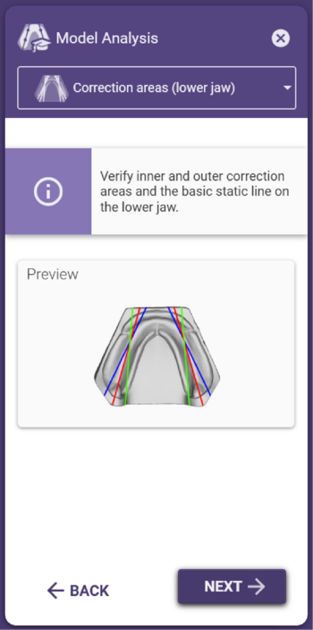
하악 수정 영역
내부 및 외부 영역을 확인합니다.
|
|
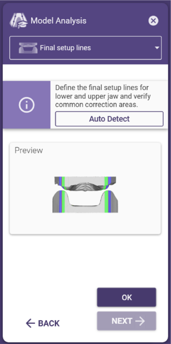
통계 기반으로 자동 계산, 확인 및 수정
모델 분석의 마지막 단계에서는 이미 정의된 점과 선으로부터 자동 설정의 기초로 사용되는 공통 통계 기반으로 계산됩니다. 이 단계는 모든 결과가 시각화되고 정확성을 다시 확인할 수 있는 모델 분석의 마지막 단계입니다.
• 마법사 바 또는 '이전' 버튼을 사용하여 탐색하여 모델 분석의 각 개별 단계를 조정합니다.
파란색 표시는 외부 조정 영역을, 녹색 표시는 내부 조정 영역을 나타냅니다. 최종 라인은 모델에서 빨간색 선으로 나타납니다.
|
단일 아치 모델 분석
|
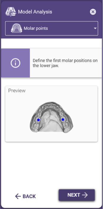
대합치의 제1대구치 위치 설정
• 대구치의 위치를 표시하기 위해 클릭합니다.
• 필요한 경우 포인트를 드래그하여 이동합니다.
|
|
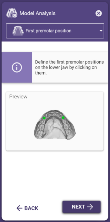
대합치의 제1소구치 위치 설정
• 클릭하여 소구치 위치를 표시합니다.
• 필요한 경우 포인트를 왼쪽 클릭하고 드래그하여 이동합니다.
|
|
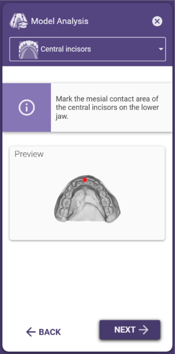
대합치의 중앙 설정
• 클릭하여 대합치의 전치부 중앙 접촉점을 정의합니다.
• 필요한 경우 포인트를 왼쪽 클릭하고 드래그하여 이동합니다.
|
|
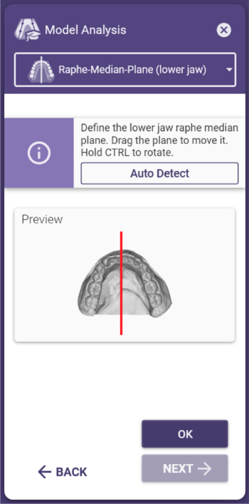
대합치의 중앙선 설정
• 대합치의 정중선이 자동으로 결정됩니다.
• 중앙선을 클릭하고 드래그하여 이동합니다.
• 회전 지점을 중심으로 중앙선을 회전하려면 Ctrl 키를 누른 상태에서 드래그합니다. 회전점을 클릭하고 끌어서 위치를 이동합니다.
|

