Model segmentation


Contents
When using the model with plate, the next stage of the model creator is starting the segmentation process. The segmentation is very similar to the traditional technique of model and die fabrication. The wizard has two tabs, PLANES and SETTINGS.
Planes
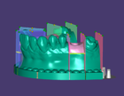
In the Planes tab there is an image of the model that can be used to toggle the segmentation/ cutting planes. These planes can be toggled on and off by clicking on the grey [A] or green dots [B]. The red dots [C]cannot be changed and are to ensure a cut between stump/die and healthy/adjacent tooth. Click Set all gingiva types to expand the options Gingiva mask [D] and Model analog (preconditioned gingiva) [E] and select which one applies to the situation. Please note that Set all gingiva types is grayed out if there is no scanbody or lab analog in the scan.

Settings
If the settings have been changed, click the Run button.
In Settings tab you can adjust the parameters that affect the model itself.


|
- Cut Width

- Plate Clearance

- Pedestal Height

- Thickness around the Pin

- Shape Parameter

- Gingiva Mask Gap

- Implant Support Width

- Model analog horizontal and vertical offset

| Moving the plane horizontally left click on the yellow control point b and drag to the correct position. To rotate the plane left click on the green control point a on the labial/ buccal or the lingual side. To angle the plane hold down crtl+shift and left click on the colored plane surface. |

| In Implant models, you can move the gingiva flat bottom vertically by moving the c plane. |

Once this is done the model design is completed, and the output files have been saved in STL format. If you have an antagonist, clicking 'Next' in the wizard will take you to the model design step for the antagonist model.