Model Design

WarningThis page documents exocad's software releases from 2023 on. See documentation for older versions


Model Creator Plateless ModelWatch the video tutorial: Model Creator Plateless Model

Model CreatorWatch the latest improvements: Model Creator

Model Design: Models without Plate

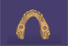
When using the model without a plate, the next step of the model creator is building the model and separating dies that fit within the model. The wizard is now in the model design and has three tabs, DIES, MASKS and SETTINGS.

Dies

Below you find the Dies tab parameters. In each parameter, you can use the arrow [A] to open the side menu to individualize the values for each tooth. Choose a tooth using the left click. By default all teeth are white [B] with the reference value set. If you individualize a value, marked in yellow, you will have a new row with the tooth selected [C]. Each time you select a tooth and change the value [D] it's marked in orange.

250 1.ModelDieWithBoreProcessorControl.gif
Plateless model design 01.png
  • 1 The height of the key pin. 250 2.ModelDieWithBoreProcessorControl.gif
  • 2 Determines how far the preparation margin is extruded vertically towards the bottom plane above the concavity. 250 3.ModelDieWithBoreProcessorControl.ModelSeatingAreaWidth.gif
  • 3 Width of the bottom seating area of the dies. 250 4.ModelDieWithBoreProcessorControl.ModelDieShaftTaperAngle.gif
  • 4 Defines the shape of the die, set 0 ° for a straight die or > 0 ° for a tapered die. 250 5.ModelDieWithBoreProcessorControl.ModelDieShaftTaperHeightLimit.gif
  • 5 Determines the height limit of the taper. 250 6.ModelDieWithBoreProcessorControl.ModelOmitDiePin.gif
  • 6 Excludes the pins from the dies. 250 7.ModelDieWithBoreProcessorControl.ModelConcavity.gif
  • 7 Remove or Add the concavity below the margin preparation.
    Plateless model design -02.png

    250 8.ModelDieWithBoreProcessorControl.ModelTiltedDieIsSkewed.gif

  • 8 Parallelizes the die bottom to the model base. 250 9.ModelDieWithBoreProcessorControl.UniformDieAngle.gif
  • 9Uniform die insertion direction. 250 1.ModelDieWithBoreProcessorControlS.gif
  • 10 Spacing between a die and the model base in horizontal (x and y) direction.
  • 250 8.ModelDieWithBoreProcessorControl.ModelBottomPinGrooveDepthCheckbox.gif

  • 11 Adds indentations in the base of the model exposing the pins for easier removal. See image Add pin Grooves 250 9.ModelDieWithBoreProcessorControl.ModelBottomPinGrooveWidth.gif
  • 12 Determines the width (i.e. x and y direction) of the pin grooves on the bottom of the model.
  • 250 10.ModelDieWithBoreProcessorControl.ModelBottomPinGrooveDepth.gif

  • 13 Determines the depth (i.e. z direction) of the pin grooves on the bottom of the model.
  • 14 Set the insertion axis of all the dies from the view into a common direction.
  • 15 Click Create model after changing a parameter, to calculate the model.
  • Once the calculation has finished, the output .stl files will be saved in the Project Directory.

    TipAs an end user of the software, you shouldn't have to fiddle with the parameters at all. You should get optimal results using the default presets provided by your system integrator, or using the presets provided by the supplier of the manufacturing equipment or production center. If not, please let your system integrator and/or manufacturing equipment vendor know!

    Masks

    Gingiva MaskWatch the video tutorial: Gingiva Mask

    Plateless model design Mask 1 Galway.png
    The Masks parameters are: 250 1.ModelDieWithBoreProcessorControlb.gif

    • 1 Minimum thickness of the gingiva mask.

    250 2.ModelDieWithBoreProcessorControl.ModelGingivaMaskGapWidth.gif

    • 2 Spacing between the gingiva mask and the model base.
      Plateless model design -03.png

    250 3.ModelDieWithBoreProcessorControl.ModelGingivaMaskImplantTopOffset.gif

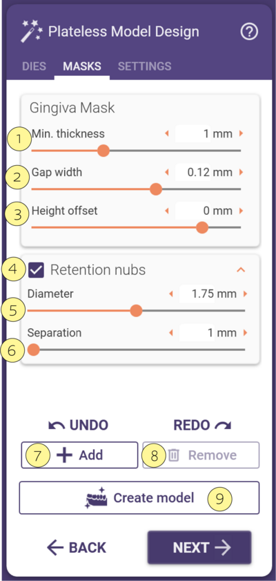
    • 3 Determines the height offset of the gingiva mask.

    250 4.ModelDieWithBoreProcessorControl.ModelGingivaMaskRetentionBallDiameterCheckbox.gif

    • 4 Check box to create retention nubs.

    250 5.ModelDieWithBoreProcessorControl.ModelGingivaMaskRetentionBallDiameter.gif

    • 5 Determines the diameter of the retention nubs.
    Plateless model design Mask Galway retention nubs.png
    • 6 Determines the space between the retention nubs. A larger value will reduce the amount of nubs.

    250 6.ModelDieWithBoreProcessorControl.ModelGingivaMaskRetentionBallSeparation.gif

    • 7 Click Add to draw the margin of the gingiva mask.

    • 8 Click Remove to delete the existing gingiva mask to create a new one.

    • 9 Click Create model after changing a parameter, to re-calculate the model.


    TipIn case the die has an extreme insertion direction, this may affect the final outcome as shown in [A]. In order to avoid it, please change the insertion direction of the die [B] or redraw the gingiva avoiding the problematic area [C]. Note that for lab analogs with an extreme insertion direction redrawing the gingiva is the only option.
    Gingiva tip.png
    Freeform gingivaSee how it's done: Freeform gingiva

    Flat Mask

    Flat MaskWatch the video tutorial: Flat Mask

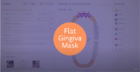
    • To create a flat gingiva mask, select as Model Type Plateless model [1] and then below it gingiva masks flat [2].

    Flat 3.2 1.png

    • Once you are in the step "Plateless Model Design’’ Tab ‘’ MASKS’’, select Add [3] and click on the Jaw [4] you want to create the Mask.

    Flat 3.2 2.png

    • After clicking, you will see automatically the jaw from an occlusal view. Click [5] to draw the area you would like to create a flat mask.

    Flat 3.2 3.png

    • Double-click to generate the flat mask [6].

    Flat 3.2 4.png

    • The flat mask [7] can be editable using the control points [A], lines [B], and mask inner area [C]. These are editable with hotkeys as described below. After editing the flat mask as desired, click Create model [8] to apply.

    Flat 3.2 5.png

    HotkeyHold click + drag - move the mask in all directions
    Shift + click on the inner mask - move the mask on the z axis
    Ctrl +click on the mask inner area - rotate the mask
    Click on the top or bottom edge/line of the mask - change the height of the mask
    Ctrl+ click on the control point - also change the height of the mask
    Ctrl + click on the top or bottom edge/line of the mask - add another control point
    Double click on the top or bottom edge/line of the mask - add another control point
    Left click + hold + right click simultaneously on the control point - remove control point
    Click + del on the control point -remove control point
    Ctrl + shift + click on the inner area - tilt the mask

    Click the Keyboard icon [9] to access the hotkey list on the software.

    Flat 3.2 6.png
    • To continue click Next [10].

    Flat 3.2 7.png


    Settings

    The Settings tab parameters are:

    Plateless model design -04.png
  • 1 Select printer preset. Right click for advanced options.

  • 2 Select material preset.

  • 3 Automatically Save preset on exit.

  • 250 2.ModelDieWithBoreProcessorControlS.gif

  • 4 The mounted base height. See image Pedestal Height
  • 250 3.ModelDieWithBoreProcessorControlS.gif

  • 5Uniform die insertion direction. 250 4.ModelDieWithBoreProcessorControl.ModelDitchWidthCheckbox.gif
  • 6 Check box for activating/deactivating the ditch.
  • 250 5.ModelDieWithBoreProcessorControl.ModelDitchWidth.gif

  • 7 Determines the width of the ditch around the stump.
  • Plateless model design -05.png

    250 6.ModelDieWithBoreProcessorControl.ModelDitchDepthAvg.gif

  • 8 Determines the average depth of the ditch around the stumps. Since the bottom of the ditches is made almost flat, the depth cannot be met exactly everywhere.
  • 250 7.ModelDieWithBoreProcessorControl.ModelDitchHeightAvg.gif

  • 9 Determines the average height of the ditch around the stumps.
  • 250 11.ModelDieWithBoreProcessorControl.ModelWallThicknessCheckbox.gif

  • 10 Check box for activating/fabricating hollow model. If the Hollow model check box is checked, the wall thickness [15] of the hollow model can be adjusted by using the slider for a precise value.
  • 250 12.ModelDieWithBoreProcessorControl.ModelWallThickness.gif

  • 11 Wall thickness of the model. If the wall thickness is 0, the model will be solid. You can also achieve that by unchecking the Hollow model.The positive number means the model will be hollow and will define the material thickness. Negative value is invalid. See image Wall thickness.
  • 250 13.ModelDieWithBoreProcessorControl.ModelWallBottomSill.gif
    Plateless model design -05.png
  • 12 Adds an extension in wall thickness towards the bottom of the model. This increases the surface area in contact with a printer build plate and adds strength to the model walls. A value of 0 removes the still feature. See image Bottom sill
  • 250 14.ModelDieWithBoreProcessorControl.ModelWallMorphologicalClosureDiameter.gif

  • 13 Determines the size of a ball that needs to fit into the cavity of a hollow model. Any region where such a ball would not fit is filled with material. Negative values are invalid.
  • 250 15.ModelDieWithBoreProcessorControl.ModelMillingHeadDiameterCheckbox.gif

  • 14 Activate the checkbox Anticipate milling.
  • 250 16.ModelDieWithBoreProcessorControl.ModelMillingHeadDiameter.gif

  • 15 The diameter slider, determines the size of the bevel at the bottom of the separate dies, and the holes in the model base allow for milling residue in the opposite part. This will be displayed as Anticipate Milling.Use the slider [20] o change this value.
    • 16 Click Create model after changing a parameter, to re-calculate the model.

    Here's an illustration of the areas affected by the respective parameters:

    • Pedestal Height
    PedestalHeight.png


    • Pin Grooves
    PinGroove.png


    • Bottom sill
    Sill.png


    • Wall thickness
    WallThickness.png

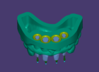
    Model Analogs

    The Analogs tab allows you to define specific parameters.

    Plateless model design -07.png Plateless model design -08.png
  • Uncheck the option [17] Toggle all teeth simultaneously to select a different option by clicking on each tooth. If you selected a gingiva mask for a tooth you will see it in pink [A]. Click on the tooth to change it to Abutment [B], note that you can have an abutment die (blue) or an abutment/gingiva (lilac) in case the gingiva is pre-selected. The preconditioned (yellow) with one click will turn to unconditioned [C] (green).

  • Check the option [17] Toggle all teeth simultaneously to select the same option for all teeth.

  • 250 17.ModelDieWithBoreProcessorControl.ModelImplantLabAnalogOffsetHorizontal.gif

  • 18 Model Analogs allows you to change the offset between the model and lab analog if it is configured in the Model Creator lab analog library. Use the slider to adjust the Horizontal offset.

  • Adjust the Width [19] to guarantee a minimum amount of material around the analog.

  • Define the Depth on gingiva mask using the slider [20].

  • 21 Click Create model after changing a parameter, to re-calculate the model.

  • Nav Need more help? Contact your reseller or book a personalized training session in our webshop.