Bar Module Split Bar

Overview
This page shows how to use the Split Bar feature. It enables the design of a suprastructure and the underlying bar in one workflow, then automatically splits the design into two precisely fitting parts. Below you will find a step-by-step description using the Demo case Split denture Bar.
Required add-on modules
Step-by-step
Open the DentalDB Application and create a new project. Then, define the job for individual teeth as usual.

Under Work Type, select Anatomic waxup/Pontic waxup and in Options & Parameters, on the section Design Bar? select Yes, in wizard to have the Bar design option during the Wizard workflow. Click Ok and apply the same selection to the other teeth. Save the project and click Design to open DentalCAD.

On the DentalDB, you can also select the Demo case Split denture bar and open on DentalCAD the waxup design finished.dentalCAD scene file saved to avoid starting from scratch and jump into the Split bar feature quickly. Below you will find a step by step using the demo sample. Click Design to start DentalCAD.

The wizard starts at the Freeforming step, allowing adjustments to the waxup.

Then, you enter the Bar Design Split Tab. A notification pops up with general instructions on how to proceed. You can use all the Bar tabs to adjust the bar profile as usual.

- To Add curve [1], click on the waxup to draw. To close the curve double click.


- [2] Modify curve - You can edit the curve moving the control points. Add a point clicking the blue line and remove a point holding left click and using the right click simultaneously.
- [3] Adjust center to edit the bar position in relation to the waxup.
- Expand the menu to see Bar adaptation options [4] to select one.
- Under the Adjust center profile curve [5] use the Make the bar curve flat [6] or Reset curve to default [7] design.
- [8] Undo or Redo buttons
- Below you can find an example of the different Bar adaptation options with default values for the following bar design.
Bar design

Bar adaptation options
 [A] Ignore the actual 3D bar design shape that has been made and generate an automatic bar design using the guiding curve of the bar (top-center curve) and the parameters
 [B] If there is enough space available it tries to follow it as an approximate guiding surface.
 [C] Tries to follow the bar design, including the pillars, which may cause the anatomic surface to be bigger when the minimum thickness is applied.
 [D] Tries to follow the bar design, excluding the bar pillars, which may cause the anatomic surface to be bigger when the minimum thickness is applied.
| Start with default values before adjusting parameters. Try to generate a bar and adjust one by one in order to understand the impact on your design. Each parameter behaves differently according to the Bar adaptation option. |

- [9] Gap thickness between both parts (relevant for calculation surface position). A higher value reduces the bar height.
- [10] Gap smooth radius - This parameter affects the edge at the top of the bar. If the value is set to 0.0 mm the edge will be rounder, if set to a higher value it will be sharper. This parameter has only an influence in case the shape of the bar for split denture is considered.
- [11] Min. side angle -The (approximately) minimum angle of the side of the dynamically generated hybrid bar surface. It affects the top edge and the walls of the bar. If this angle is set to a high value e.g. 15° the walls will be "straighter".
- [12] Bar boundary radius – Affects the diameter/radius of the bar
- [13] Horizontal boundary factor that is multiplied with the bar boundary radius (0 means almost no boundary, 1 means to target a rather spherical boundary, 2 to target a very wide boundary)
- [14] Horizontal boundary size shift in mm that is applied to the bar boundary
- [15] Minimum thickness (anatomic) ensures the minimum thickness selected to the anatomic part.
- [16] Minimum thickness (bar) ensures the minimum thickness selected to the bar.
- [17] Minimum boundary thickness of the bar (lower part) ensures the minimum thickness for the boundary.
- Click [18] to Delete all split curves and Apply [19] to use the parameters selected.
- After you achieve the desired bar design, click Next.

- Entering the Free-Form Bar step, you can edit the bar. Note that you can expand the following menu to ‘’’Keep bottom surface fixed’’’ which keeps the boundary untouched/fixed.

- Continuing the workflow, you can now design the Waxup Bottom. Here select the cement gap between both parts.

- In the next step wait for the waxup calculation.

- Make the necessary adjustments using the Freeforming tool.

- Clicking next, you reach the Merge and Save restorations where it cut out the screw hole automatically.


Tips
| Tip 1 - To maintain the minimum bar thickness near screw access holes, enable Use 3D shape more exactly. This preserves the bar pillars and helps ensure the Min thickness (bar) constraint is respected around the holes. |
Tip 2 For a successful design, ensure the center guiding curve is well-positioned, use a precise split curve with well-aligned control points, and give the bar enough height for stability without making it excessively high. For a successful design, ensure the center guiding curve is well-positioned, use a precise split curve with well-aligned control points, and give the bar enough height for stability without making it excessively high. |
| Tip 3 - If you need to free-form the framework/bar, please make sure you don’t create undercuts to avoid changing the insertion axis. Otherwise, redrawing the margin will be necessary.
 |

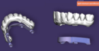
Tip 4 - To illustrate how the parameters can affect the output bar, image 1 shows an example without a shoulder and the corresponding parameters, while image 2 shows an example with a shoulder. These are for demonstration purposes only. Image 1 - example without a shoulder Image 1 - example without a shoulder
 Image 2 - example with a shoulder Image 2 - example with a shoulder |
Q&A
Can I use any type of profile to design the bar?
Yes. You can start with any profile type to design the bar. After creating the bar, apply the bar adaptation options which consider the design.
The height of the bar is very short compared to the structure. Which parameter can influence this?
The Gap thickness parameter can affect the bar height. If the gap is too large, the bar may appear shorter relative to the structure. Reducing the Gap thickness value can help increase the bar height in these cases.
Keep in mind that the final cement gap between both structures is calculated later, so you can adjust it precisely during the finishing steps.
The result of the bar has some holes. What can I do?
Start by adjusting the Gap thickness parameter. A higher gap value increases the risk of creating holes in the bar. Reducing this value usually helps eliminate those gaps. After adjusting, regenerate the bar and check the result.
While designing the bar I realized the waxup I did does not have enough space for bar and structure. Can I edit the wax up still?
To edit the waxup, enter Expert Mode, then right-click on the waxup and select Free-forming. You can modify the waxup using the available Free-forming tools. Once you’ve made the necessary adjustments, reopen the Bar Design by right-clicking in the context menu and adjust the bar accordingly to your needs.