Contents
You can select and visualize a DICOM series record for your patient for visual support for designing the prosthetic component. Note: The software is not intended for diagnostic purposes.
With the help of the DICOM Control, you can load a DICOM series and define visualization settings. To open the DICOM Control, click Tools in the main toolbar and select DICOM Control.
- Click Select file set to open the DICOM Series Selection Dialog.

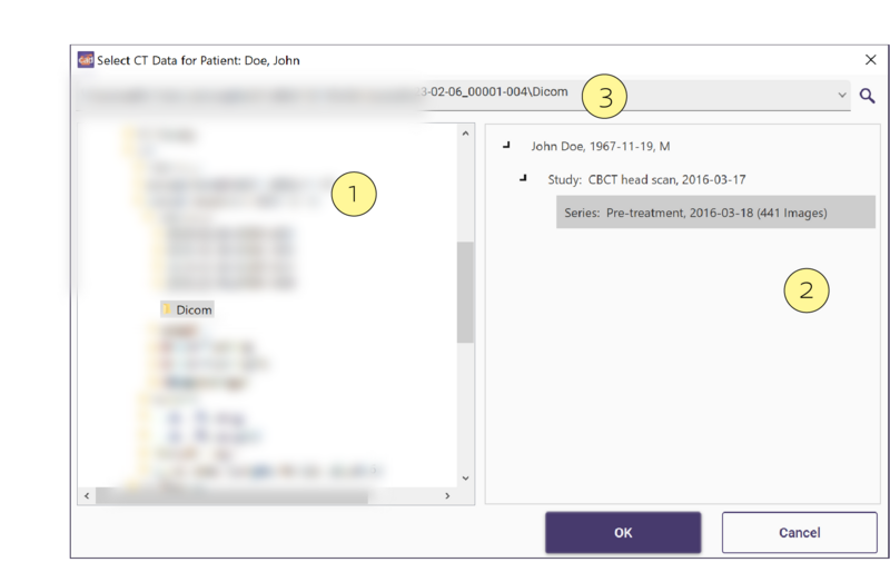
If you have loaded a project file containing the patient's name, the dialog’s title will display it. Select the directory that contains the DICOM series you want to visualize: browse the directory in the navigation section [1], or drag a folder from a separate explorer window to the CT data analysis section [2], or paste the directory’s path into the navigation line [3].
The software automatically analyzes the selected file directory for existing CT data. The content of subfolders is not considered in this analysis.
Ideally, the information in the CT data analysis section contains all items to identify a patient, which are the patient’s name (name and surname), the patient’s sex, the patient’s birth date, and the date by which the study and series were recorded. However, the information depends on the availability of the corresponding DICOM tags in the selected data. The CT data analysis section can provide less information about the CT dataset than the Data tab in the DICOM Control. If the CT data analysis section does not provide the specific information you are looking for, check if you find it in the Data tab of the DICOM Control after loading a series.
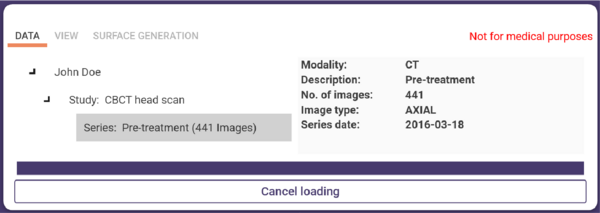
Select a DICOM series in the analysis section (selecting a study/patient is not possible). Click OK. The DICOM series is being loaded. You can abort the loading process by clicking Cancel loading.
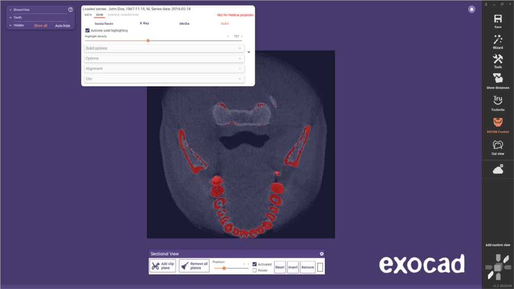
The loaded DICOM series is visualized in the main view.
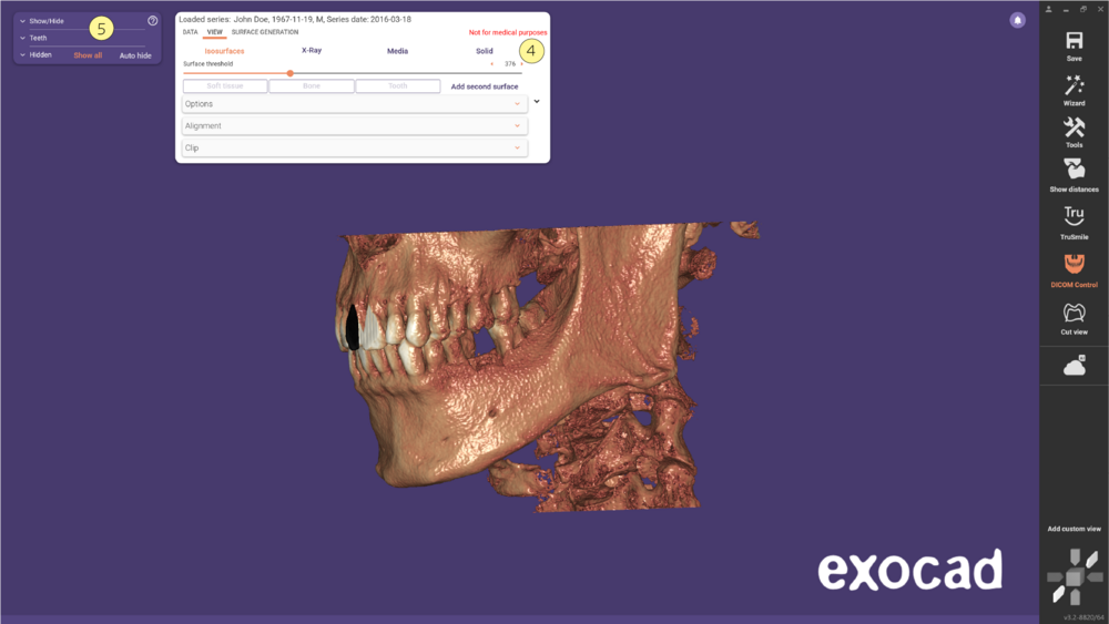
[4] DICOM Control
[5] Group Selector with CT data group
You can modify the visualization of the DICOM series using the options and settings in the DICOM Control. To show/hide the DICOM Control, click DICOM Control in the main toolbar.
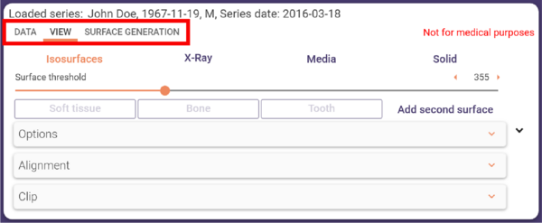
- Data:CT dataset information
- View:visualization parameters and options
- Surface Generation:options to generate surfaces from the isosurface visualization.
You can reduce/extend the DICOM Control window using the icon > on the right.

Data Tab
The Data tab shows all available information about the visualized CT dataset and extracts this information from the dataset, not the project file.
 [6] Structure of the CT dataset (patient, studies, series)
[7] Patient/study/series information (depending on left-side selection)
- Select file set: Open the DICOM Series Selection Dialog, for selecting a different series to load.
- Load series: Load the series currently selected in the CT dataset structure (left side).
- Discard series: Discard the currently loaded series.
View Tab
The View tab provides options and settings for visualizing the DICOM series.
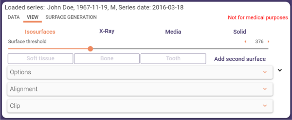
- Isosurfaces: Visualizes the DICOM series as a surface generated from the CT data and contains precisely those voxels with a density value equal to a selected surface threshold value.
- X-ray: Visualizes the DICOM series in a way that simulates a conventional X-ray exposure, considering only those voxels with a density value higher than a given noise threshold value.
- Solid: The DICOM series is rendered as a solid cube. Each voxel on its face is grayscale-colored according to the local density value. You can cut the cube to visualize the area of interest.
- Media button: used to view the Dicom data in HQDD or (High Quality Detail Definition)
Isosurfaces
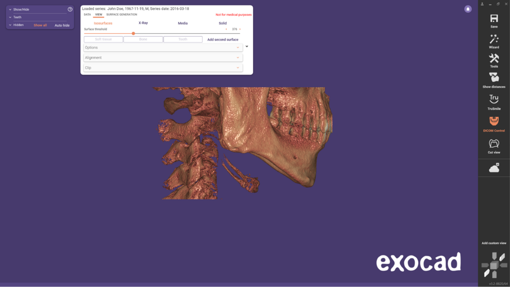 Surface threshold: Use this slider or type in a value to define the density value of the anatomical structure displayed as a surface.
X-ray
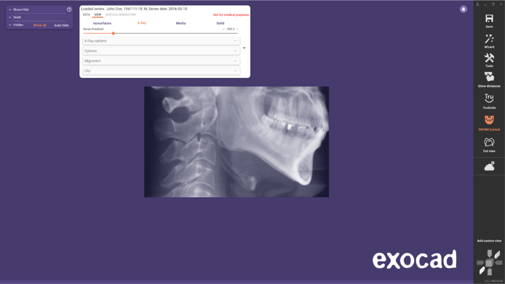 Use the Noise threshold slider or type in a value to define which voxels are displayed in the X-ray visualization. Voxel data lower than the specified value is not taken into account.
Solid
- Activate solid highlighting: By default, solid highlighting is deactivated. Check Activate solid highlighting to activate the Highlight density slider.
- Highlight density: Use this slider to define a threshold value that determines which parts of the visible anatomic structure are highlighted in red. All data values higher than the defined value are highlighted.
- Solid Options: Hard to soft Use this slider to smooth the border between highlighted and unhighlighted regions when solid highlighting is activated.
General Options for All Visualization Modes
Options
Using the Current CT data window slider, you can define the range of data used for the visualization. These settings influence contrast and brightness in the Solid visualization mode. Using the triangle icon, you can choose from available CT data window presets. Available presets are defined in the DICOM dataset. <Full Range> is always available, which extends the CT data window to the full range of available data values.
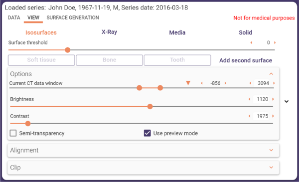
Available checkboxes:
- Semi-transparency: Set the DICOM series visualization to half transparent. Deactivates the Add second surface button in visualization mode Isosurfaces.
- Use preview mode: Activated by default. In preview mode, the accuracy is reduced during camera movements or visualization parameter adjustments. If your PC is high-performative, you can deactivate the preview mode to maintain the highest possible accuracy during camera movements and slider adjustment.
Clip
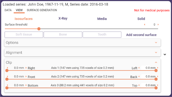 You can cut away a section of the DICOM series visualization in three directions from both sides by using the corresponding range sliders or entering values.
Surface Generation Tab
The Surface Generation tab is only available in visualization mode Isosurfaces. It enables you to create surface meshes from the currently visible isosurface.
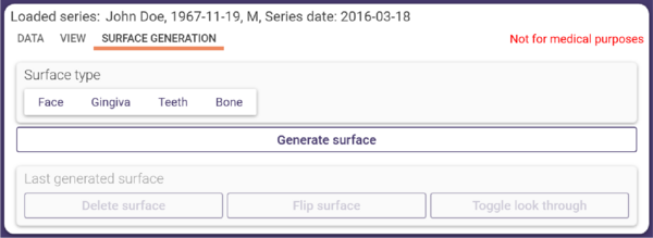 To create a surface mesh, follow these steps:
- Step 1: Define the surface you want to create a mesh for using the surface threshold slider in the View tab while in visualization mode Isosurfaces. For example, to create a mesh representing the bone structure, define a threshold value where the bone structure is visible.
- Step 2: Select the Surface Generation tab.
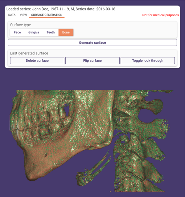
- Step 3: Click Generate Surface. A triangle mesh is now created from the currently displayed view.
After loading a scene or project and generating a mesh, it appears in the Group Selector as CT surfaces group.
To create further surfaces, repeat steps 1 to 3. Each created surface will be displayed in its own color.
As soon as you have generated at least one surface, the following functions are available at the bottom of the Surface Generation tab, each affecting only the last generated surface mesh:
- Delete surface: Delete the last generated surface.
- Flip surface: Change the surface’s orientation (back and front).
- Toggle look through: Display only the front side of the surface.


