Setting insertion axis


Contents
Insertion Direction
You will not always get prompted for the insertion axis. The software can accurately autodetect the proper insertion axis in the vast majority of cases. You will be asked to check the detected insertion direction in the following cases:
- When constructing bridges for 3-axis or 4-axis milling
- For 3-axis milling, it is required - due to production constraints - that all teeth within a bridge have the same insertion axis. The detected common insertion axis is shown to the user, who can then optimize this sometimes difficult decision.
- When the software has doubts about the insertion axis it auto-detected
- Even for single crowns/copings, or for bridge elements in 5-axis milling, you are sometimes prompted to verify/correct the detected insertion axis. This is usually the case when dealing with dubious preparations (e.g. when the margin line lies within an undercut area).
- For all inlay constructions

Checking/Editing the Insertion Axis
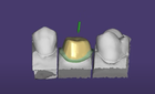
The software will present you its auto-detected insertion axis by adjusting the viewpoint so that you look onto the preparation(s) from the insertion direction. Additionally, undercuts will be marked with a color scale.
Setting a New Insertion Axis
To change the insertion axis, rotate the view so that you look onto the preparation(s) from your desired insertion direction. Then, click Set current view as insertion axis [4] to set this as the new insertion axis. To change the insertion axis manually, drag the sphere [5] at the tip of the arrow displayed above the preparation(s) accordingly to the desired position. The Undercut visualization [3] will be updated.
Applying a Common Insertion Axis for Several Constructions
 In 5-axis or laser melting mode, the software allows different insertion directions for parts within a bridge. To enforce the same insertion axis for several parts, click the respective tooth within the tooth selection control [1]. Click on the tooth symbol 46 to ensure that teeth 44 and 46 share the same insertion axis. Click 46 again to undo.
Check Unique insertion direction [2] for bridges to enforce a common insertion axis for all parts of the currently edited bridge (default in 3-axis mode).
| In 3-axis mode, uncheck this box only if you really know what you're doing. |
When you are finished defining the insertion axis, click 'Next' in the Wizard window to proceed to the next step.