Nesting Actions
The second way is to launch the CAM application either from the Dental DB top button bar CAM Button or from the icon on the desktop. In the Nesting actions window (1) you can directly add files by clicking on the import button (3) pull up a previous file by clicking on the show queue button(4)
Here in the Nesting Actions section there are 4 buttons at the top : Clear(1),Save(2), Show Queue(3),Import(4)
Nesting Queue
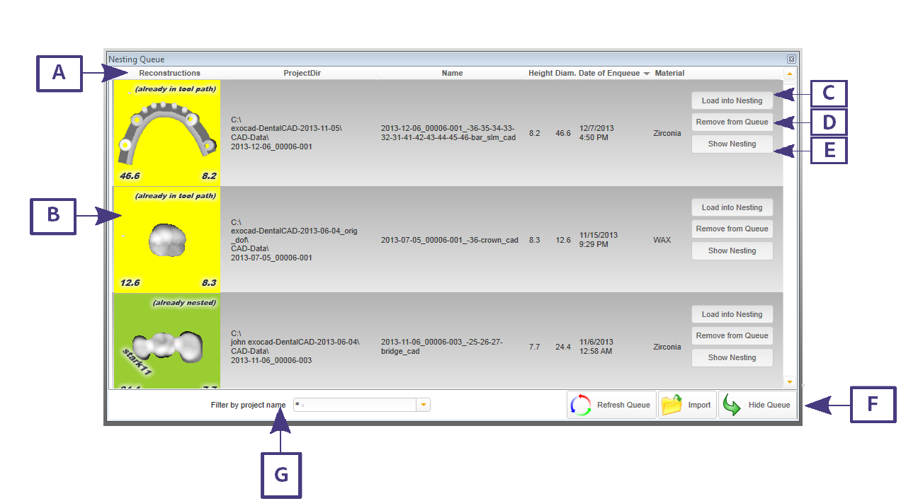
When clicking the show queue button or if it is already visible when you start the CAM application. We are able to see parts which are in the queue to be positioned in the material of choice and are ready to proceed to CAM or have already been through the CAM process.
A: Headings for the sections of the part. Reconstructions, Project Directory, Name(of File) Height(of reconstruction), Diameter (of Reconstruction), Date of Enqueue, Material.
B: The part which is to be or has been processed
C: Load into Nesting button
D: Remove from Queue button
E: Show Nesting button- this will allow you to see this specific part in its respective material block/puck
F: Refresh Queue, Import and Hide Queue buttons
G: Search filter - Filter by project name
| In the Nesting Queue you will see 4 different colors which indicate a nesting/nested reference: Grey, the part is ready for nesting ( has not been nested). Green , the part has already been nested and a tool path has been generated. Yellow, the part is in the block/puck and a tool path has been generated and milled or the file is ready to be milled (.cnc file ready for processing). Red, all depending on the thickness or height you have chosen the part displayed may not fit into the blank /puck and may need to be rotated to fit. |
Importing into CAM
To import a file(STL) to be inserted, click on the Import button in section 1 of the Nesting Actions section, see "ExoCAM Module" or drag and drop the 3D model(stl) onto the Import button
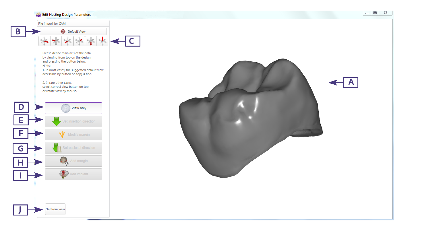
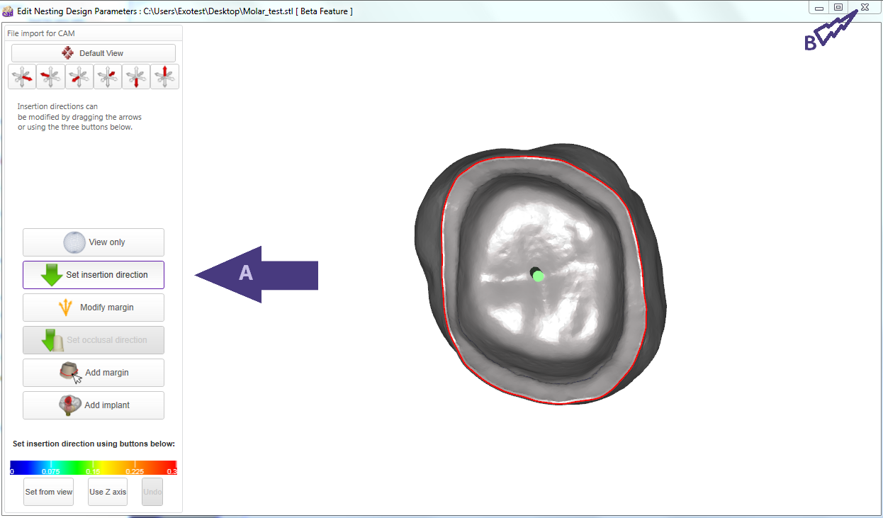
This will open a window in explorer to allow you to find the file to be processed. Once you choose a file a new window will open. You will see the 3D model(stl file) here in the view area (A). You are now able to begin the file import for CAM. you can at this point click on the default view button (B) usually this will set the 3D model(stl) from the occlusal view if this is not the case set the 3D model(stl) to the occlusal view and click on the set from view button (J).
A: Here is the area to view the file you imported(stl)
B: This is a default view button
C: These buttons are for a specific view
D: This is the view only button
E: This allows the setting of the insertion direction
F: This allows the modification of the margin
G: This allows the setting of the occlusal direction
H: This allows the addition of a margin to a 3D model (stl)
I: This allows the addition of an implant(abutment)
J: This allows the setting from view
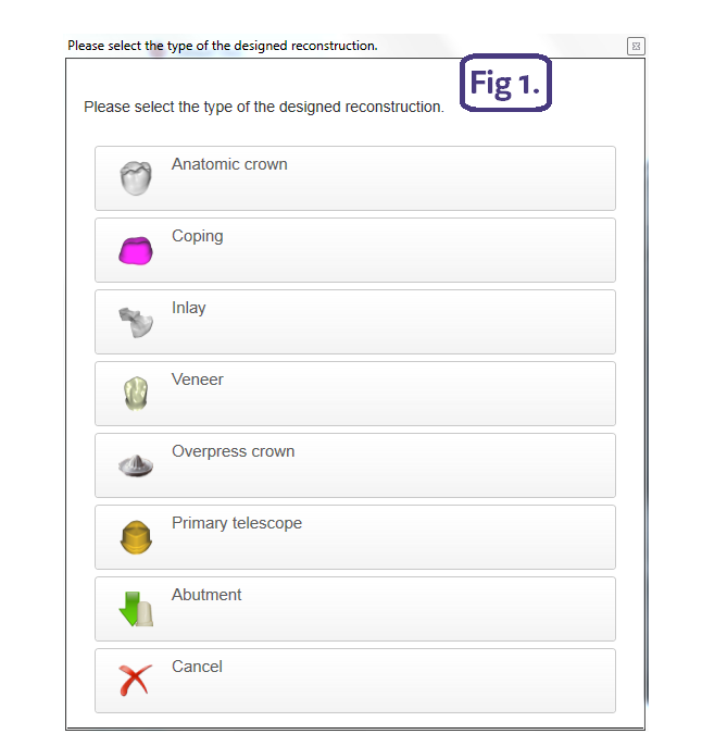
Now you will see a new window which will allow you to select the type of the designed reconstruction. (Fig 1.)
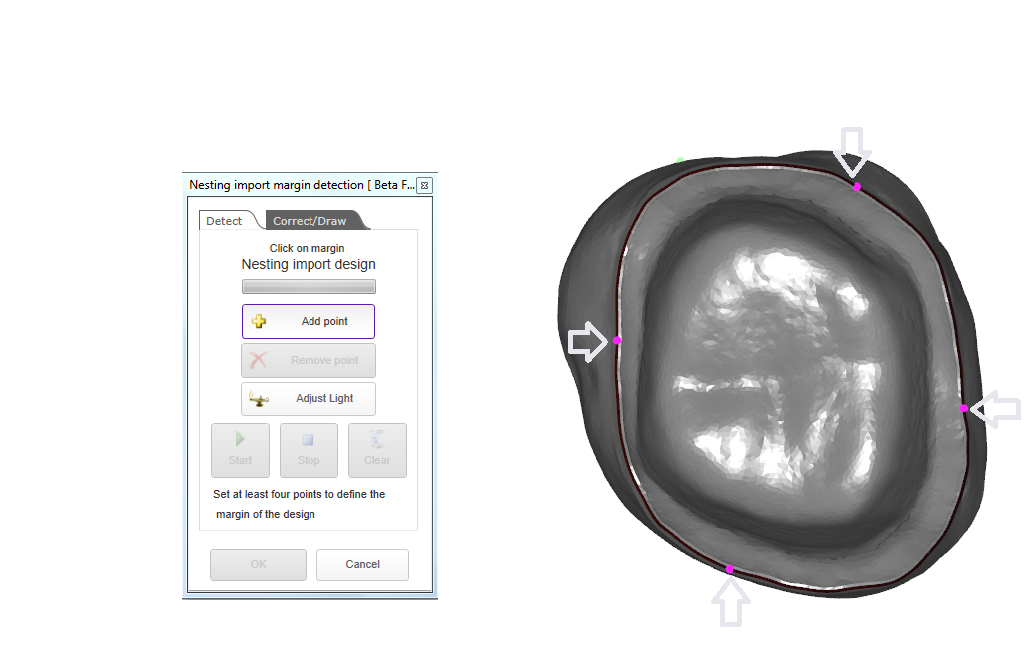
Once the type of designed reconstruction is chosen the Add margin button (H)is activated, and a new window will pop up which is basically the same as the Wizard margin detection tool see "Detect / edit margins". Here you now need to set at least 4 points as you would for an inlay, or veneer.
As you can see here once the margin is set it will be red. Here you can now set the insertion direction of the 3D model by using the green arrow or by setting the 3D model from the marginal view and then clicking on the Set insertion direction button (A). Once this is done close the window(B).
Here you will now see a window Closing Edit Construction Window you can accept and use all changes in current nesting , reject and discard all changes or cancel. If you choose accept and use all changes in current nesting it will then send the 3D model(stl) to the 3D Nesting View
see "ExoCAM Module".
Block/Puck and Reconstruction Placement Parameters
These buttons here are related to the first section on this page Nesting Actions
(A) Height of Reconstructions: self explanatory
(B) Show Orbit checkbox: visualizer of orbit Show Colliders checkbox: visualizer of Colliders
(C) Quick position view: changes the view of the material block
(D) CAM Vendor and machine list
(E) Configure Tool : This varies with CAM vendor( see ExoCAM Tool configuration)
(F) This allows you to visualize the undercuts if there are any.
(G) This is to begin the CAM calculation See
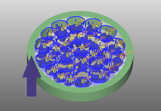
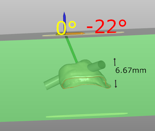
| The reconstructions can be moved, rotated or angled into the material type/block selected by the Arrange by Mouse button (5)this button works in conjunction with the Arrange Planar and Keep 4-axis arrangement check boxes. The unchecking of the "Arrange Planar" box allows the unit to be placed at a different height within the material block and also allows a tilting when using the CRTL button on the keyboard and clicking the left button on the mouse. The unchecking of the Keep 4-Axis arrangement box allows the rotation of the unit when using the CRTL button on the keyboard and clicking the left button on the mouse |
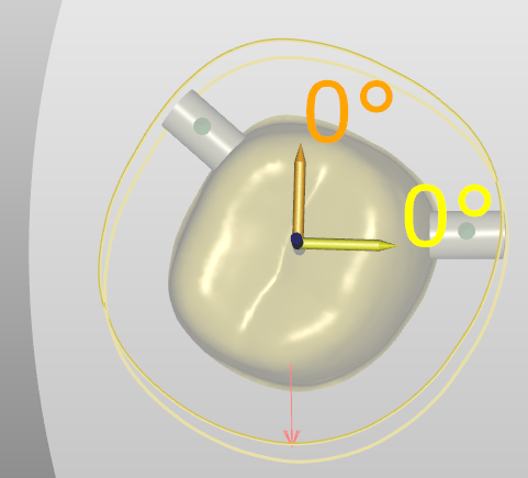
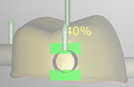
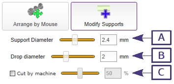
| The supports can be altered by the Modify Supports button(6). Once pressed the supports can be altered by size(diameter)using the support diameter slider, you can add supports by clicking on the reconstruction/unit and dragging away towards the edge of the spacing around the reconstruction/unit. To delete the support you can right click on the support and choose remove support or simply by pressing the CRTL key on the keyboard and clicking on the left mouse button. The amount of the support to be cut by the machine can also be adjusted to facilitate easier removal of the unit/s from the puck. |
When you choose the Modify Supports button, you will see 3 sliders Support Diameter(A) , Drop Diameter(B) and Cut by Machine(C),the cut by machine slider is activated when the checkbox is checked.

