Screw hole design


For a screw-retained bridge, it can be helpful to design the screw channel to be extended above the actual framework. This way, the ceramic can't flow into the screw channel holes and the milling burr will not chip the ceramic.
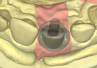
Each screw channel in the tooth arch can be individually selected and referenced to the anatomy (white-colored), the framework (green-colored) or to have no screw channel at all (yellow-colored). You can toggle between the modes by clicking the individual teeth.
Alternatively, you can use the Anatomy[1] and Framework[2] buttons to decide a global default for all screw channels.
The screw channel default parameters are Thickness [3] and Height [4]. They are controlled by typing a value or by adjusting the slider. Height values above zero make the screw channel higher than the anatomy, values below zero shrink the screw channel lower than the anatomy.

Snap All Off [5] will automatically unstick all screw channels allowing you to move freely the control points.
The green arrow [6] allows moving simultaneously all the control points vertically.
Adjusting the screw channels
The screw channels have control points with toggle disks. Adjusting the screw channel control points can override the height and thickness parameters, but the minimum thickness of the channel will always be applied. If the toggle disks below the control points are black, this means that the control points are fixed in their height to the anatomy.

You might want to change the thickness individually and selectively to one or more control points. In this case, you can click on the arrow by the control point, hold the mouse button and drag it outside, away from the center to your preferred value.
If you want to increase the thickness in one direction, e.g. mesial/distal/oral/vestibular, click on the arrow which you define as the center of range movement at the control point, hold <SHIFT> and drag the part of the screw channel to the desired thickness.
| If you want the same thickness all around the screw channel, you can click an arrow at the control point, hold <CTRL> and drag the border of the screw channel outwards. |

You can switch to free movement mode by clicking the toggle disk. The color switches from black [8] to green [7]. Now you can move this control point in all directions, only the minimum thickness will remain fixed.
To unlock all control points, choose a locked control point and hold <CTRL> while clicking the toggle disk. Now all points change to free movement mode. You can now individually lift them to any height by dragging the green point in the middle of the screw channel as you desire.
| While pressing <CTRL> and clicking the big green control point in the middle of the screw channel [6], you can flatten the top of the screw channel. |
| You can get a summary of all available commands by holding the mouse cursor over the purple "i" in the little Wizard window on the left upper edge. |