Dental DB Application
The entry point to the CAD/CAM platform is the DentalDB module. Here, you define your job (dentist, patient, technician, the type of constructions and the materials). All the tasks you will perform to finalize your CAD/CAM work are started from here: Scanning, construction, upload of construction data or milling.
Contents
Getting started
After startup, the following screen is presented to you:
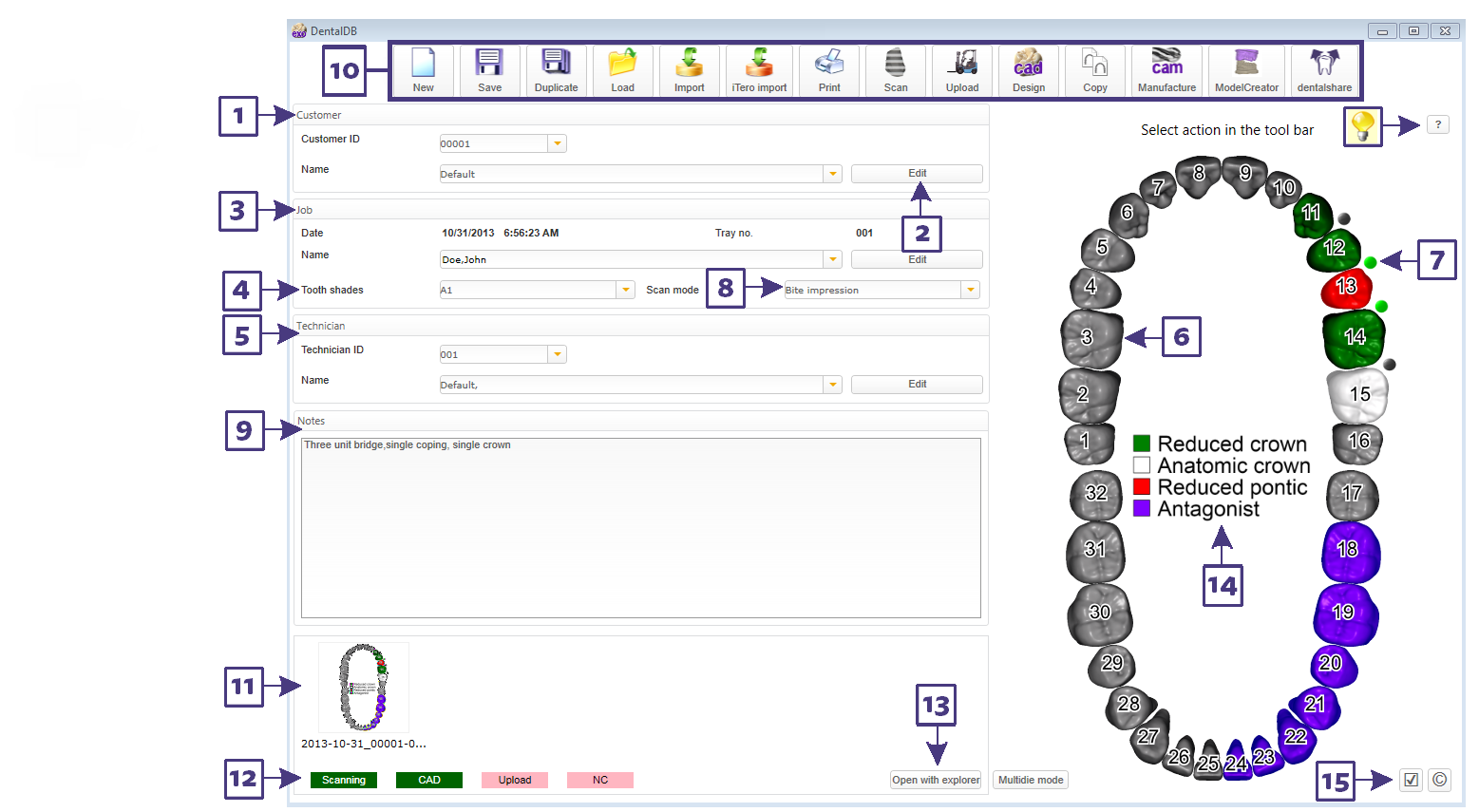
| A short help text in the upper right, above the tooth bow, will guide you step-by-step |
Defining job details
To define your job, proceed as follows:
- Select the customer (dentist) [1]. You can either select the customer number or the customer name; the respective other field will update accordingly.
- To add a new customer to the database, click the "Edit" button [2] – a dialog will open that allows you to view your list of dentists.
| In the Customer window at the customer ID pulldown[1], you can start typing the first characters of a customer name, and the selection will autofill ("typeahead find") |
- Select the name of the patient [2]
| You can also type in a new patient name in the field [3] – the new name will automatically be added to the database as soon as you save your job. |
- Select technician (the same way as you select the customer)
- Select the restorations and materials by clicking on the tooth bows [6] – see "Chosing tooth restoration types" for details. Colors are used to mark different types of restorations in the tooth bow; an index is available [14].
- To use an antagonist scan, select "Antagonist" for at least one tooth in the opposing jaw opposing your restorations, and define the type of antagonist scan/ scan mode using [8]
- Define connectors using the toggle buttons [7].
- Green: A connector will be created between the teeth
- Grey: A connector will not be created between the teeth (click to toggle)
- Red: A connector may not be created, because the material of the adjacent teeth differs
- No toggle button present: One of the selected types does not permit connectors
By default, connectors will be defined automatically whenever you define a pontic. So in practice, you will use this feature mostly to add connectors between adjacent crowns or copings.
- You may also select tooth shade [4] or other job details (depending on your configuration, options like express shipping from the milling center may be available).
- Notes field, add additional information here [9].
Saving and starting actions
Once your job is defined, click the "Save" button in the button bar [10] to save your job. This will add the job details to the database, and create a project folder which will hold all the data (scans, constructions, project file) related to this job.
Once the job has been saved, additional buttons in the button bar [10] become available: You may now start the scanning process using the "Scan" button, and then start the CAD construction using the "CAD" button, or print job details using "Print".
Note that content of the button bar, as well as the icons for the various actions, may vary depending on your system configuration.
Buttons for:
- duplicating a job (copying job information/scan data/construction data and saving it in a new project)
- importing jobs (e.g. project directories you have received from a partner lab)
- uploading a job to the production center (once the construction has been completed)
- launching the CAM module or the machine control software
- other features offered by your system vendor may be available on your setup
The red/green indicators [12] give you an overview which actions have already been performed. Green color means that this stage of the process (Scanning, CAD, etc) has been completed. To open the respective project directory in Windows Explorer, click the "Open in Explorer" button [13].
Loading saved jobs
To load a job, click "Load" in the button bar [10]. See the "Loading Jobs" section for details.
The image preview pane
For saved jobs, an image preview panel [11] is available. After the scan process, preview photos of the models will be visible here.
| You can use Drag & Drop functionality to add additional images of your choice. E.g. you can drag and drop patient photos from a digital camera or from your email client directly here [11]. Double-click an image thumbnail to open it in your favourite image viewer, right-click it to access its context menu (the same menu that is available for the image in Windows Explorer) |
Changing user interface language and tooth numbering scheme
Button [15] opens a configuration dialog which allows you to change the language of the user interface, and switch between FDI tooth numbering (11-48), Universal Numbering System (1-32, US) or the Palmer Notation system -quadrant based.