Partial Framework CAD Workflow - Abbreviated Version

The Partial Framework CAD tool allows a free work flow, where you can arbitrarily jump between different steps of the design. However, as a new user, we suggest that you try to follow the design process as shown below:
Contents
- 1 Survey
- 2 Remove blockout in undercut areas
- 3 Relieve rough areas
- 4 Draw curves on refractory model
- 5 Major Connector relief
- 6 Add Design Elements in Wax
- 7 Rest seats, minor connectors, and lingual apron
- 8 Finish lines
- 9 Filling in voids and smoothing
- 10 Tissue Stops
- 11 Support Bars (only required for 3D printed resin patterns)
- 12 SAVE FOR BUILD
Start by loading a scan(default), or browse/select between scans and .partialCAD scene files saved previously. You can save scenes by Ctrl + S or right-click in the background (context menu).
Survey
When a new case from scan is loaded, the default tool is Survey ![]() . The model will appear blue with a WHITE arrow
. The model will appear blue with a WHITE arrow  indicating the path of insertion (POI). Left-click the mouse anywhere on the model,the arrow turns RED when activated, then drag the mouse to tilt the model. When you release the mouse, the colors update to show the new undercut depths. You may want to change the Draft Angle to 2 or 3 degrees ( default is 0 ) in the dynabar at the bottom of the screen, whichever is common practice. Click the Add To Blockout
 ![]() icon in the dynabar to proceed and apply calculated blockout wax.
Note: To view the undercut color's depth settings, click on Settings in the dynabar. You are able to change the top ( red ) setting / value. The middle ( lime green ) setting will always be automatically adjusted to be half ( 50% ) of the top ( red ) value. Notice the colors will change position on the model after you press Enter.
icon in the dynabar to proceed and apply calculated blockout wax.
Note: To view the undercut color's depth settings, click on Settings in the dynabar. You are able to change the top ( red ) setting / value. The middle ( lime green ) setting will always be automatically adjusted to be half ( 50% ) of the top ( red ) value. Notice the colors will change position on the model after you press Enter.
Secondary Blockout can be added using the Block Out Selection tool ![]() .
- To change the Draft Angle with same path of insertion: Use the dynabar default Mode:Select Area, with the green ball tool to paint select an area where you want secondary blockout, at a different angle. Set the new Draft Angle degree in the dynabar. Apply, then click on the Add To Block Out icon
.
- To change the Draft Angle with same path of insertion: Use the dynabar default Mode:Select Area, with the green ball tool to paint select an area where you want secondary blockout, at a different angle. Set the new Draft Angle degree in the dynabar. Apply, then click on the Add To Block Out icon ![]() in the dynabar.
- To change the POI: Tilt the model using Left-click and drag (POI arrow turns red). In the dynabar, change the Mode to "Set Path", then Apply, then click the Add To Block Out icon
in the dynabar.
- To change the POI: Tilt the model using Left-click and drag (POI arrow turns red). In the dynabar, change the Mode to "Set Path", then Apply, then click the Add To Block Out icon ![]() , in the dynabar.
, in the dynabar.
Remove blockout in undercut areas
The Smudge ![]() tool is automatically presented . Left click and drag it to remove beige blockout wax in the areas near the base of involved teeth, where clasp tips will be placed in the undercut. When finished with all those areas, click Apply,
tool is automatically presented . Left click and drag it to remove beige blockout wax in the areas near the base of involved teeth, where clasp tips will be placed in the undercut. When finished with all those areas, click Apply,![]() and the beige wax will convert to blue block out wax.
and the beige wax will convert to blue block out wax.
| color scale shows the depth of undercuts |
 To view the undercut color scale, click on Settings in the dynabar. You are able to edit the values by changing the top ( red ) value. This automatically adjusts the middle value ( lime green ) to 50 % ( half ) of the top value.
Relieve rough areas
| The +, - keys or Ctrl+mouse wheel, change the tool size. The Ctrl+Z / Ctrl+Y give you access to multi-level undo/redo. This might take a little time to get used to, since these keys aren't used in the classic exocad DentalCAD software |
The software defaults to use Automatic Relief under the Major Connector ONLY . To check it, right-click in the background, select Options, and then select Save For Build. Note checkbox status. However, you may still find it neccessary to add additional relief wax over rough areas.
For MANUALLY adding relief wax, use the Smooth ![]() tool, click on Melt
tool, click on Melt ![]() , the first sub icon in the dynabar. Be sure to check the box, "Smooth with Mask" , then left-click and drag, to add a light coat of wax over:
, the first sub icon in the dynabar. Be sure to check the box, "Smooth with Mask" , then left-click and drag, to add a light coat of wax over:
- rugae and rough areas of an upper, or
- the lingual and posterior ridges of a lower, or
- at the base of involved teeth, in the free gingiva areas. Or you can use the same procedure for Lowers, described below.
.
| Do NOT be concerned with the Major Connector palatal area of an Upper (yet). You can approach that with our automation method, after you have drawn a Major Connector curve. |
For a Lower lingual bar, use the orange Paint Filler ![]() tool, click on the Select sub icon
tool, click on the Select sub icon ![]() in the dynabar, the default Smooth Level is set to the 2nd hash mark from the left,
in the dynabar, the default Smooth Level is set to the 2nd hash mark from the left, ![]() and sweep ball across the lingual area where the bar will be designed.
and sweep ball across the lingual area where the bar will be designed.
| In either case, complete step by converting wax to blockout using the Add To Block Out icon. |
To fill in recent extraction sites, use the blue Fillertool. ![]() Draw a closed curve around the extraction socket. Click on the Filler tool and click on the curve that encloses the region to be embossed ( filled ) with wax. Adjust the dynabar slider to the far right, click Apply. Then use the Add To Block Out sub icon
Draw a closed curve around the extraction socket. Click on the Filler tool and click on the curve that encloses the region to be embossed ( filled ) with wax. Adjust the dynabar slider to the far right, click Apply. Then use the Add To Block Out sub icon ![]() to convert that beige wax to blue blockout wax.
to convert that beige wax to blue blockout wax.
Draw curves on refractory model
Use the Draw Curve tool ![]() , which will default to the first sub icon Create Edit Point Curve
, which will default to the first sub icon Create Edit Point Curve ![]() , left-click edit points while dragging the mouse on the model to draw curves. Ctrl+Z is the undo key. Double left-click to end an open curve / Single left-click on the start edit point to end a closed curve.
You may want to experiment with the second method of drawing a curve by using the second sub icon Create Traced Curve
, left-click edit points while dragging the mouse on the model to draw curves. Ctrl+Z is the undo key. Double left-click to end an open curve / Single left-click on the start edit point to end a closed curve.
You may want to experiment with the second method of drawing a curve by using the second sub icon Create Traced Curve ![]() , which after the start edit point, enables you to drag the mouse , laying down a curve without edit points. To access the edit points, to adjust the curve, use the Select tool
, which after the start edit point, enables you to drag the mouse , laying down a curve without edit points. To access the edit points, to adjust the curve, use the Select tool ![]() and click on that curve. Create a closed curve by ending on the first/start point with a single click.
You can move a group of edit points by left-clicking anywhere outside the curve, and dragging a rectangular region around the edit points. Click on any green point to move the entire group. Click on an orange point to exit this mode.
and click on that curve. Create a closed curve by ending on the first/start point with a single click.
You can move a group of edit points by left-clicking anywhere outside the curve, and dragging a rectangular region around the edit points. Click on any green point to move the entire group. Click on an orange point to exit this mode.
- Major Connector of an upper - Create a closed curve around the Major Connector, going through the middle of the bead line, if appropriate.
- Lingual bar of a lower - double clicking to complete (close) the curve.
- Mesh areas - draw as a closed curve, being careful to overlap, but not to connect the major connector curve.
- Clasps - You can define one-sided clasps by drawing a curve from the apex of the clasp to the end of the clasp in the undercut. Opposing clasps on the same tooth can be defined by either the same continuous single curve or two separate ones. For two and three curve clasps, the same order in which the lines are drawn is used when applying the 2 or 3-curve Clasp types, so be consistent!
- Minor Connectors - Draw a curve starting close to the Major Connector to a point in the interproximal.
| SAVE OFTEN, SAVE EARLY, AND SAVE OFTEN! SAVE along the way (Ctrl + S or Right click on the background) |
Major Connector relief
IF you have "Automatic Relief" option turned off ( unchecked ) in the Options ( right click in the background > Options > Save For Build )then you can opt to add Manual Relief by selecting the orange Paint Filler ![]() tool. In dynabar, Smooth Level defaults to the second hashmark from the left, and the inset should be set to 2 mm, then
you Left-click on the Major Connector curve. Then, click on the Add To Block Out Tool:
tool. In dynabar, Smooth Level defaults to the second hashmark from the left, and the inset should be set to 2 mm, then
you Left-click on the Major Connector curve. Then, click on the Add To Block Out Tool: ![]() to convert all added relief wax to block out wax (look for blue color)
to convert all added relief wax to block out wax (look for blue color)
| DO NOT forget this last step or this added wax will become part of your design wax. |
Add Design Elements in Wax
- Upper Major Connector or Lower Lingual Bar
- {Select the Mesh Connector tool
 , then Left-click on the Major Connector curve. The orange I.D. tags should properly label each closed curve as a Connector, Mesh, Tissue Stop or Hole.
- {Select the Mesh Connector tool
Verify this, and then click on Preview to view the mesh. It will render and automatically proceed to apply the wax. 
For lower lingual bars, select the BAR tool ![]() leave room on the ends of the bar for Finish Lines to contact, and turn off the end caps in dynabar check box. It will render and automatically proceed to:}
leave room on the ends of the bar for Finish Lines to contact, and turn off the end caps in dynabar check box. It will render and automatically proceed to:}
- Mesh Areas
- For each Upper mesh area, left-click on the ball of the vector arrow, use the interactive circle to rotate the black&white mesh control to the desired orientation. Use the vector arrow head tip with a drag motion to resize the preset holes. Click on Settings to choose between Round or Square( Diamond )holes, or Smooth with no holes and / or adjust size numerically. Also choose your Connector Pattern from the drop down and set the value for the Stipple Thickness. Click on Preview to view the current settings, then click on Apply to finish.
For each Lower mesh, select the Mesh Tool ![]() , click on the mesh curve, one at a time and repeat the previous procedure until all meshes are generated / applied.
, click on the mesh curve, one at a time and repeat the previous procedure until all meshes are generated / applied.
| If an ibar clasp will be used in your design, rotate the mesh holes so that there is a linear path to the clasp arm approach angle. |
| SAVE AGAIN, SAVE EARLY, SAVE OFTEN ! ... SAVE along the way (Ctrl+S or Right click on the background ) |
- Clasps
- Select Clasp tool
 , use the drop down in the dynabar to choose the appropriate clasp Profile
 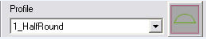 and to the left, the appropriate clasp Type
 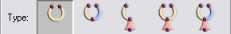 .
.
- Select Clasp tool
| If you choose a multi- curve clasp, you MUST left click on the curves in the same sequence that you drew them to apply the preview. |
 Click on Settings to change the clasp preset size (Width), if desired. Note: Clasp will taper toward the end which was drawn last. You can Swap Ends by clicking on that tab.

If you want to utilize a complete Bucco-Lingual clasp, you can use the Width check boxes in Settings, to make both ends taper. Now the thickest part of the clasp will be at the clasp's midpoint(i.e. at mesial or distal wall)
| IF you are incorporating an ibar, in Settings, enter a value for Approach in the Offset Above Surface dialog box. This will allow the approach arm to sit off the tissue surface. This is NOT necessary however, if the survey heavily applied block out wax in that area already! You do not want to double the spacing. |
- Minor Connector
- Select either theClasp tool or the Pipe Tool
 , then click on each Minor Connector curve, set the diameter, adjust the preview by dragging edit points, then click Apply to create the Minor Connectors in wax.
- Select either theClasp tool
- Post
- Select the Add Post tool.
 Click on the area of a mesh where you want the post to be attached. A preview is presented with an green ball on top. Left-click on the orange ball, which will activate the interactive mode, displayed by multi-directional arrows, showing that you can tilt the post in any direction. Note: if you have the post on an anterior mesh, you can rotate the model to a view that allows you to align it with the angle of an adjacent tooth. In the dynabar, adjust the Height and Width before you Apply.
- Select the Add Post tool.
- Post Retention
- Retention can be added to the post in several manners. The first method, probably the easiest, is to select the Smudge tool
 reduce to a small tool size, and remove wax on the sides of the post. The second method would be to use the Clone tool
  with the tool size adjusted to approximately 0.5mm. With Ctrl depressed, left-click on the sides of the post to add small retention beads to the post.
  The third method would be to use the Draw Curve tool
  to draw a curve around the post in a downward spiral direction. ( This will resemble screw threads )
  This can be tricky and may take practice, as you have to rotate the model. Note: it is best to pull the pencil ( Draw Curve tool )away from the post while rotating the model. After ending the curve, click on the Pipe tool
  , in the dynabar, adjust it to a diameter of 0.5mm, then choose the Create Pipe and Subtract icon
  . Left-click on the spiral curve. The preview will have edit points if you need to adjust the preview. Click Apply.
- Retention can be added to the post in several manners. The first method, probably the easiest, is to select the Smudge tool

- Emboss Logo, Name or Numbers
- First, you must use Microsoft PAINT to create your lab's name and Save it in Pictures, Documents or Desktop, etc. Note you need to make the background black and the lettering white !
 Select the Emboss Areatool
  In the dynabar, click on the checkerboard icon SelectandEmbossPattern
  This will open a window to allow you to Browse to the location of your logo file you created. Select your logo. The logo is now blue and can positioned on the model over the desired area. Left-click to apply the image onto the wax surface. In the dynabar, select Raise ( + ) or Lower(-),
  then either click on Preview or Apply. If necessary, Ctrl+Z will undo.
- First, you must use Microsoft PAINT to create your lab's name and Save it in Pictures, Documents or Desktop, etc. Note you need to make the background black and the lettering white !


Rest seats, minor connectors, and lingual apron
Use the Clone Tool ![]() . Set thickness, then left click and drag to apply that fixed thickness of wax in the desired areas.
. Set thickness, then left click and drag to apply that fixed thickness of wax in the desired areas.
| You can dimple rest seat surface using the Smudge tool |
Finish lines
Draw curves ![]() for the Finish Lines atop smoothed palatal wax. Note: End the curve(s) shy of the desired ends of the Finish Line wax to allow for the tapered extension.
Next, select the Finish Line tool
for the Finish Lines atop smoothed palatal wax. Note: End the curve(s) shy of the desired ends of the Finish Line wax to allow for the tapered extension.
Next, select the Finish Line tool ![]() , click on one finish line curve at a time. ( Note: the second profile in the Profile drop down has a much smaller lingual bulge ) Left-click on the handle's orange ball to use the interactive circle to rotate the preview, folding it over toward the mesh. ( Note: this handle is only present when viewing the model from the front or rear view. Apply when satisfied.
Use Smudge
, click on one finish line curve at a time. ( Note: the second profile in the Profile drop down has a much smaller lingual bulge ) Left-click on the handle's orange ball to use the interactive circle to rotate the preview, folding it over toward the mesh. ( Note: this handle is only present when viewing the model from the front or rear view. Apply when satisfied.
Use Smudge ![]() , Smooth
, Smooth ![]() and Tug
and Tug ![]() tools to reduce the lingual bulge of the finish line. Tug tool can also be used to fold over the lip of a Finish Line.
tools to reduce the lingual bulge of the finish line. Tug tool can also be used to fold over the lip of a Finish Line.
| You are able to create your own custom finish line profile. Click on the Edit Profile icon |
Filling in voids and smoothing
to fill in spaces / voids between wax.
| When designing, if you neglected and area or notice a new area that will require block out wax, you can use the Smooth tool |
Since you have existing design wax on the model, you can NOT just convert it to block out by using the Add To Block Out icon. You must select the green Select Wax with Ball tool ![]() and paint select that area green. Then choose Add To Block Out icon
and paint select that area green. Then choose Add To Block Out icon ![]() down in the dynabar.
down in the dynabar.
Tissue Stops
Tissue stops can be created using the green Select Wax with Ball Tool ![]() . Simply move the ball to the point of the mesh where the stop is desired. Adjust your ball tool size to be larger than the thickness of BOTH the beige design wax AND the blue relief wax. The defaults would calculate at .75mm beige + 1mm blue
Left-click to paint select that area green, use the Remove From Block Out icon
. Simply move the ball to the point of the mesh where the stop is desired. Adjust your ball tool size to be larger than the thickness of BOTH the beige design wax AND the blue relief wax. The defaults would calculate at .75mm beige + 1mm blue
Left-click to paint select that area green, use the Remove From Block Out icon ![]() in dynabar, to convert the blue relief wax to beige wax.
Finally, use the Smudge Tool
in dynabar, to convert the blue relief wax to beige wax.
Finally, use the Smudge Tool ![]() to remove wax in the tissue stop area. Adjust the size of the ball appropriately. It should remove wax all the way down to expose the purple color of the refractory model. Then Ctrl+Z to replace the wax.
to remove wax in the tissue stop area. Adjust the size of the ball appropriately. It should remove wax all the way down to expose the purple color of the refractory model. Then Ctrl+Z to replace the wax.
Support Bars (only required for 3D printed resin patterns)
Click on the Draw Curve tool ![]() . In the dynabar, choose Fit to Clay On Create tool
. In the dynabar, choose Fit to Clay On Create tool ![]() to deselect it, ( tool background turns WHITE ), which allow you to draw curves in free space, across the arch.
Next, select the Pipe tool
to deselect it, ( tool background turns WHITE ), which allow you to draw curves in free space, across the arch.
Next, select the Pipe tool ![]() . In the dynabar, set the diameter to 2mm , click on the Create Pipe and Add icon
. In the dynabar, set the diameter to 2mm , click on the Create Pipe and Add icon ![]() then click on the unfit curve(s). Here, you ARE allowed to click on all the curves prior to Applying all the Support Bars.
then click on the unfit curve(s). Here, you ARE allowed to click on all the curves prior to Applying all the Support Bars.
 Support Bar positioning is critical. They are NOT to be placed randomly. The purpose of the positioning is to prevent the printed resin framework from warping, post print. A Best Practices Guide to placing support bars is provided.
| Light cured resin printed patterns ARE still light sensitive and reactive ! Post cleaning process, we suggest that you keep them in a dark box, until time of investing. If you are laser sintering, obviously, this is not an issue |
SAVE FOR BUILD
by RIGHT clicking in the background, and left-click Save For Build. Be patient, as you wait to see the blue progress bar at the bottom of the screen, to run across, left to right.
This will result in a gray image of the .stl  You are able to rotate the .stl.