ModelCreator
Model Alignment
The exocad Model Creator is used to design 3D physical models from scan data. Both quadrant and full-arch articulated models are easily created from any kind of scan. In the case of articulated scans, it is assumed that the scans are in centric relation when creating the model. Later you can add a physical articulator hinges to each model.
To invoke the Model Creator, specify the desired restorations in the DentalDB. Crowns and Pontics will automatically be segmented. Later in the workflow, you can override the automatic selection of which die(s) will be separately removable.
Launch the Model Creator from the button in the DentalDB action menu.
The first wizard step specifies the type of model to be created. There are two types of models, called "with plate" and "without plate", or "plate-less". "With Plate" models are similar to sectioned stone models, each section slides over a pre-manufactured (pin) base plate which is configured in the model creator settings. "Without Plate" models have removable dies embedded in a base with adjacent/healthy and gingival scan data. These models can be created "hollow". The workflow for each type of model is slightly different, both are described below.
| The Model Creator settings for specific printers or mills are set by the reseller, and should be established prior to using the Model Creator |
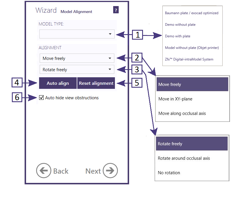
The available model types [1] are reseller-dependent, but may include:
- Baumann plate /exocad optimized - a 3rd party plate is available from Baumann (http://www.baumann-dental.de/) available as Part number 1970010 - "pin base plate / small"
- Demo without plate - an example of a plate-less model
- Demo with plate - an example of a model with a made-up plate
- Model without plate (Objet printer) - plate-less direct printing of models (optionally with removable die(s))
- Zfx Digital-intraModel system - special system available from Zfx
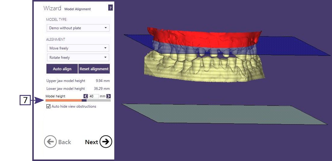
After the Model Type is selected, the scans will appear between two parallel planes, representing the boundaries of the model. These boundaries can be either flat for plate-less, or your selected pin base.
Scan data beyond this boundary will be "clipped". Red shading indicates that a section of the scan lies outside the defined planes/plates, while gold indicates the scan data area to be used.
To easily position the scans within the model boundary, click on [4] Auto align. If the resulting position of the scans is not the intended one, you can left-click on the scans, with the left mouse button, to freely move it or right-click and drag to freely rotate the scans into the model boundary. You can also limit the range of motion using the [2] Move and [3] Rotate drop-down selectors.
Reset alignment [5] will restore the scan to it's original position before any motion or rotation was applied. Auto-hide view obstructions [6] uses an algorithm to determine when to hide one or the other arch.
| For plate-less models, the minimum height should allow for the minimum pin-size to rest in the base |
Model Alignment - Plate-less
You can also adjust the total [7] height of the models (the total distance between the upper and lower planes) dynamically, by using the slider or by entering a height into the text box. The resulting heights of both the lower and upper models are displayed.
Model Alignment - with Plate
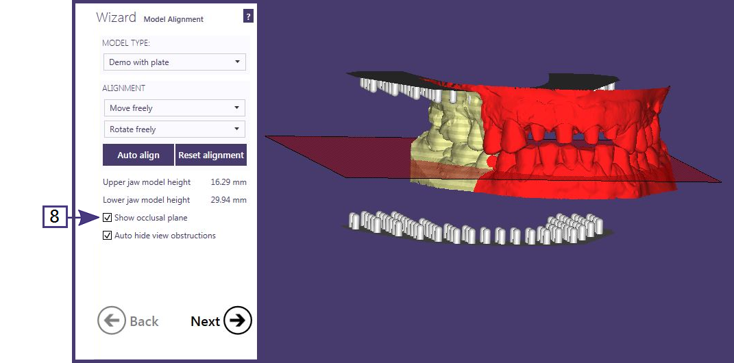
The "with plate" model editor allows you to Show occlusal plane [8] in order to determine the optimal alignment.


