New-layout-Margins
Contents
Margin Line Detection

The first step in the construction is the preparation margin detection. In most cases, the Wizard will prompt you to define the margin line for a specific tooth [2].

As you move the mouse over the scan data, a bubble will appear, showing you a sectional 2D view of the area below the mouse pointer. This helps you finding the correct position for the initial seed point for the automatic margin line detection. For crowns and related restorations, a single click will typically suffice – the automatic margin line detection will start after the first click. For inlays, four points must be set for the detection to start.
Adjusting the Light Source to Help you See the Margin
You can rotate the object so that you look at it from the insertion axis, and then click Adjust Light [7] to adjust the virtual light source so that it comes from this view point. If you look at the margin from the side afterwards, the shadows will help you see the margin.
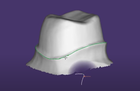
Dealing with Misdetected Margin Lines

In some cases, especially when working with non-optimal preparations, the margin line may not be detected correctly. You can help the algorithms by clicking one or more additional points on the margin line. To do that, activate Add point [3] and click points on the margin. E.g. in the graphic on the right, the user set an additional point (the purple dot) after the initial misdetection. After each point is set, the automatic detection will now take advantage of your additional points.
| Typically, adding a single point will be enough; in difficult cases 2-4 points may be required. Setting large amounts of points is unnecessary. |
If you have erroneously clicked a point which is not actually on the margin, switch to Remove point [4] and click the point/s to remove. Switch back by clicking Add point [3] to add points again.
Clearing and Starting Over
If you have clicked the wrong tooth or outside the margin, click Clear [6] to clear all defined points and start again.

Editing the Margin Line

You can edit or manually draw the margin line by clicking the Correct/Draw [1] tab in the margin detection dialog. The detected margin line changes to green and now features little dots, which grow as you move the mouse near them. These are the control points which help you edit the margin.
Different modes for editing the margin line are now available:
- Move [8]: Drag and drop individual control points.
- Add new points by clicking the green line.
- Remove points by clicking them with both mouse buttons (first hold the left mouse button on a point, and while holding it, click the right mouse button – the point will disappear).
- Up/Down [9]: Drag and drop the mouse near the margin. Control points will move up or down, as if the mouse pointer was magnetic.
- Draw [10]: Draw a portion – or the entire margin – freely. If a margin was defined previously, start drawing close to the existing margin, and add points by clicking the object. When done, click Accept drawing changes [11] to merge the newly drawn section with the existing margin line.
- Magnetic line drawing [11]: Toggle between modes where the margin line is created linearly between your drawn points, or adapted to the surface of the die. Holding CTRL will toggle between the two modes.
If you are working with sectioned models, you can check Auto-hide adjacents [15] to enable or disable the adjacent die.
No matter how you're editing the margin line – you can always go back one or more steps by using the Undo /Redo feature. When done with the margin line editing, click 'Next' to continue to the next step.

| Use the <PageUp> and <PageDown> keys to rotate for inspecting the margin line from all sides. |